Community project
Ultrasonic Companion Robot
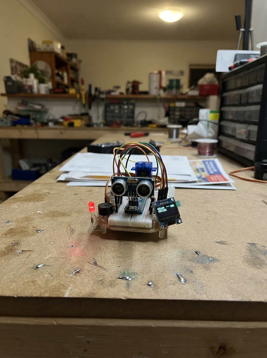
Build a cute robotic companion that watches for nearby movement using ultrasonic distance sensing. The robot features glowing LED eyes, a servo-controlled head that scans side to side, a buzzer for chirping alerts, and an OLED display showing real-time distance measurements.
This guide provides a complete wiring diagram, parts list, and step-by-step assembly instructions to bring the companion to life on an Arduino Uno. The included firmware handles distance scanning, eye animations, head movement, sound effects, and display updates—everything needed to create an interactive tabletop robot that reacts when someone gets close.
Wiring diagram

Gather all the parts
Assemble it in 7 steps
1. Place the Uno and make a ground row
Put the Arduino Uno beside a breadboard. Run one black jumper from an Uno GND pin to the breadboard’s blue or minus rail. Every part below uses this same ground row so the robot can understand its signals.
- Keep the USB socket facing outward so you can plug it in after wiring.
- Do not plug the Uno into USB until you have checked that no jumper joins the 5V rail directly to GND.
2. Build the two glowing eyes
Place both LEDs on the breadboard. For each LED, connect its short leg, beside the flat side of the LED body, to the ground row. Connect the long leg of the left LED to one end of its 220 Ω resistor, then connect the resistor’s other end to Uno D4. Repeat with the right LED and its 220 Ω resistor, but connect that resistor to Uno D5.
- Left eye: D4 → 220 Ω resistor → LED long leg (light); LED short leg → GND (ground).
- Right eye: D5 → 220 Ω resistor → LED long leg (light); LED short leg → GND (ground).
- Do not connect an LED straight to D4 or D5 — the resistor prevents too much current from damaging the LED or Uno pin.
3. Wire the distance sensor
On the HC-SR04, connect VCC to Uno 5V, GND to the ground row, TRIG to Uno D7, and ECHO to Uno D8. Point the two round sensor openings outward from the robot’s face.
- VCC → 5V (power), GND → GND (ground), TRIG → D7 (start signal), ECHO → D8 (distance reply).
- Make sure VCC and GND are not swapped — swapped power can damage the sensor.
4. Add the moving sensor head
Fit the SG90 servo horn onto the servo shaft, then attach the HC-SR04 to the horn with tape, a small bracket, or a dab of removable adhesive. Connect the servo’s brown or black wire to the ground row, red wire to Uno 5V, and orange or yellow wire to Uno D9.
- Servo black/brown → GND (ground), red → 5V (power), orange/yellow → D9 (movement signal).
- Leave enough slack in the sensor wires for the head to sweep without pulling them loose.
- Keep fingers and loose wires away from the moving horn; it can pinch or pull parts off the breadboard.
- If the Uno resets or the servo twitches erratically, stop and power the servo from a separate regulated 5V supply with its GND joined to the Uno GND; a servo can demand short bursts of current that a USB port may not provide reliably.
5. Connect the chirp maker
Connect the buzzer GND pin to the ground row and its SIGNAL pin to Uno D6. If your buzzer has a plus mark, use that marked pin for D6 and the other pin for GND.
- SIGNAL → D6 (chirp signal), GND → GND (ground).
- Do not force a marked positive buzzer pin into the ground row — reversed polarity can prevent it from making sound.
6. Wire the small status screen
Place the 0.96 inch SSD1306 OLED where it can be seen on the robot’s front. Connect its VCC pin to Uno 3.3V, GND to the ground row, SDA to Uno A4, and SCL to Uno A5. The display then shows the robot’s mood and the distance it sees.
- VCC → 3.3V (power), GND → GND (ground), SDA → A4 (screen data), SCL → A5 (screen timing).
- On an Uno, the SDA and SCL pins beside AREF are the same electrical connections as A4 and A5; use only one of each pair.
- Make sure VCC and GND are not swapped — swapped power can damage the screen.
7. Check and power the companion
Check every VCC wire goes only to its stated power pin and every GND wire goes to the ground row. Plug the Uno into your computer with USB. After deployment, the robot looks around, blinks, chirps for nearby objects, and shows its status on the OLED.
- The sensor notices objects roughly 35 cm or closer and chirps about once per second while something is in front of it.
- Unplug USB immediately if a wire gets hot, you smell melting plastic, or the board repeatedly disconnects.
Review all connections
1. Connections between "distance_sensor" and "Arduino"
2. Connections between "head_servo" and "Arduino"
3. Connections between "voice_buzzer" and "Arduino"
4. Connections between "left_eye_resistor" and "Arduino"
5. Connections between "left_eye_led" and "Arduino"
6. Connections between "right_eye_resistor" and "Arduino"
7. Connections between "right_eye_led" and "Arduino"
8. Connections between "status_oled" and "Arduino"
Deploy the firmware
#include <Arduino.h>
#include <Wire.h>
#include <NewPing.h>
#include <Servo.h>
#include <Adafruit_GFX.h>
#include <Adafruit_SSD1306.h>


// Forward declarations
void setEyes(bool on);
void chirp(unsigned int frequency, unsigned long durationMs);
void showStatus(unsigned int distanceCm, bool someoneIsClose);

const byte TRIG_PIN = 7;
const byte ECHO_PIN = 8;
const byte SERVO_PIN = 9;
const byte BUZZER_PIN = 6;
const byte LEFT_EYE_PIN = 4;
const byte RIGHT_EYE_PIN = 5;
const byte OLED_SDA_PIN = A4;
const byte OLED_SCL_PIN = A5;
const unsigned int MAX_DISTANCE_CM = 120;
const byte SCREEN_WIDTH = 128;
const byte SCREEN_HEIGHT = 64;

NewPing sonar(TRIG_PIN, ECHO_PIN, MAX_DISTANCE_CM);
Servo head;
Adafruit_SSD1306 display(SCREEN_WIDTH, SCREEN_HEIGHT, &Wire, -1);

unsigned long lastScanAt = 0;
unsigned long lastEyeChangeAt = 0;
unsigned long lastChirpAt = 0;
unsigned long lastDistanceReadAt = 0;
int headAngle = 60;
int headStep = 3;
bool eyesOn = false;
unsigned int displayedDistance = 999;
bool displayedClose = false;

void setEyes(bool on) {
  digitalWrite(LEFT_EYE_PIN, on ? HIGH : LOW);
  digitalWrite(RIGHT_EYE_PIN, on ? HIGH : LOW);
  eyesOn = on;
}

void chirp(unsigned int frequency, unsigned long durationMs) {
  tone(BUZZER_PIN, frequency, durationMs);
}

void showStatus(unsigned int distanceCm, bool someoneIsClose) {
  if (distanceCm == displayedDistance && someoneIsClose == displayedClose) {
    return;
  }

  displayedDistance = distanceCm;
  displayedClose = someoneIsClose;
  display.clearDisplay();
  display.setTextColor(SSD1306_WHITE);
  display.setTextSize(2);
  display.setCursor(0, 0);
  display.println(F("ROBO PAL"));
  display.drawLine(0, 19, 127, 19, SSD1306_WHITE);
  display.setTextSize(1);
  display.setCursor(0, 27);

  if (someoneIsClose) {
    display.println(F("HELLO, FRIEND!"));
  } else {
    display.println(F("LOOKING AROUND"));
  }

  display.setTextSize(2);
  display.setCursor(0, 43);
  if (distanceCm == 0) {
    display.print(F("No object"));
  } else {
    display.print(distanceCm);
    display.print(F(" cm"));
  }
  display.display();
}

void setup() {
  pinMode(LEFT_EYE_PIN, OUTPUT);
  pinMode(RIGHT_EYE_PIN, OUTPUT);
  pinMode(BUZZER_PIN, OUTPUT);

  Wire.begin();
  display.begin(SSD1306_SWITCHCAPVCC, 0x3C);
  display.clearDisplay();
  display.display();

  head.attach(SERVO_PIN);
  head.write(90);
  setEyes(true);
  chirp(880, 90);
  showStatus(0, false);
}

void loop() {
  const unsigned long now = millis();

  if (now - lastScanAt >= 45) {
    lastScanAt = now;
    headAngle += headStep;
    if (headAngle >= 120 || headAngle <= 60) {
      headStep = -headStep;
      headAngle += headStep;
    }
    head.write(headAngle);
  }

  if (now - lastEyeChangeAt >= 900) {
    lastEyeChangeAt = now;
    setEyes(!eyesOn);
  }

  if (now - lastDistanceReadAt >= 150) {
    lastDistanceReadAt = now;
    const unsigned int distanceCm = sonar.ping_cm();
    const bool someoneIsClose = distanceCm > 0 && distanceCm <= 35;
    showStatus(distanceCm, someoneIsClose);

    if (someoneIsClose) {
      setEyes(true);
      if (now - lastChirpAt >= 700) {
        lastChirpAt = now;
        chirp(1300, 70);
      }
    }
  }
}
Remix this project
Make it yours in one click
Open a full copy of this project in your own Schematik workspace — diagram, code, parts, and assembly steps included. Swap the sensor, add features, or redesign the whole thing with AI. The author's original stays untouched.