Community project
Control de Cultivo Aeropónico
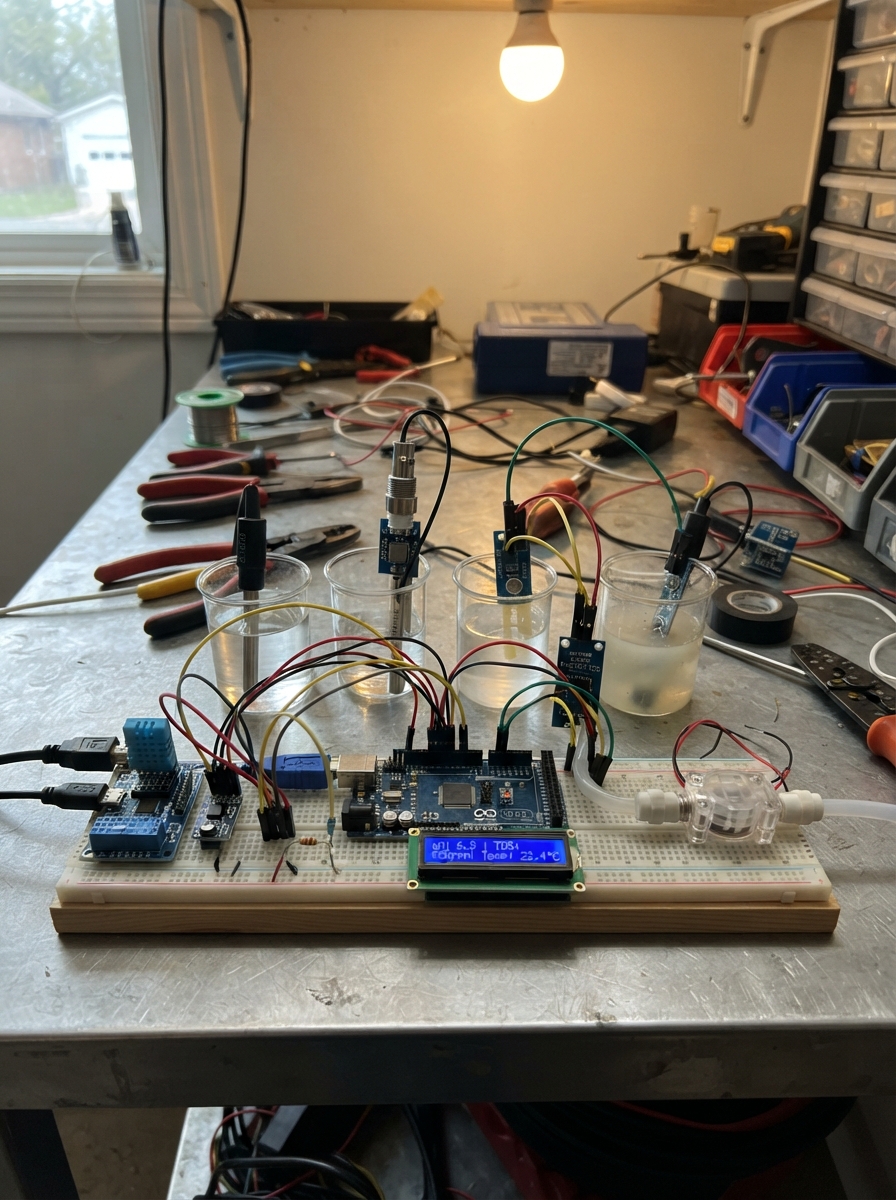
This aeroponic cultivation controller uses an ESP32 to monitor and automate a hydroponic growing system. It reads environmental conditions through light, humidity, air temperature, water temperature, pH, turbidity, and TDS sensors, while tracking water flow and reservoir level with a flow meter and ultrasonic distance sensor. The guide provides a complete wiring diagram, parts list, and step-by-step assembly instructions for connecting all sensors to the microcontroller, configuring the three-channel relay module for pump, filter, and fan control, and uploading the monitoring firmware.
Builders will learn how to integrate multiple sensor types with different voltage requirements using voltage dividers, set up I2C communication for the light sensor, configure interrupt-driven flow pulse counting, and implement relay logic for system automation. The assembly checklist ensures proper power distribution across four rails and includes pre-power verification steps to prevent component damage.
Wiring diagram

Gather all the parts
Assemble it in 7 steps
1. Prepara los cuatro raíles de alimentación
Con la placa sin conectar, reserva una fila negra para GND, una naranja para 3.3 V, una roja para los 5 V del USB/VBUS y otra roja separada para el positivo de la fuente externa de 5 V. Une el negativo V− de la fuente externa al rail negro GND: esta unión es obligatoria para que las señales de control tengan la misma referencia.
- Usa cable negro para todas las uniones de tierra, naranja para 3.3 V, rojo para 5 V y azul para señales.
- La fila roja externa no se debe unir al VBUS USB; solamente se unen sus negativos en GND.
- No conectes todavía la fuente externa ni las cargas: un positivo externo unido por error al rail USB puede dañar el ordenador o la placa.
2. Conecta los sensores de 3.3 V
Desde el rail naranja conecta BH1750 VCC, DHT11 VCC y DS18B20 VCC; desde el rail negro conecta sus tres GND. Con cables azules conecta BH1750 SDA a GPIO4 (datos), BH1750 SCL a GPIO5 (reloj), DHT11 DATA a GPIO7 (señal) y DS18B20 DATA a GPIO6 (señal). Conecta una resistencia de 4.7 kΩ entre 3.3 V y la misma unión de DATA/GPIO6 del DS18B20.
- Conecta ADDR del BH1750 a GND para que use su dirección habitual.
- La resistencia de 4.7 kΩ no tiene polaridad; sus dos patas solamente deben quedar entre 3.3 V y la línea DATA del DS18B20.
- No alimentes estos tres sensores desde 5 V: hacerlo puede estropearlos.
3. Monta los cinco divisores de tensión
Para cada salida de 5 V, coloca una resistencia de 10 kΩ desde la salida del módulo al nodo de señal y una de 20 kΩ desde ese mismo nodo al rail negro GND. Lleva cada nodo con cable azul al ESP32: pH PO a GPIO1 (señal), turbidez AO a GPIO2 (señal), TDS AO a GPIO3 (señal), YF-S201 PULSE a GPIO8 (señal) y HC-SR04 ECHO a GPIO10 (señal). Alimenta pH, turbidez, TDS, YF-S201 y HC-SR04 con VCC al rail rojo USB de 5 V (alimentación) y GND al rail negro (tierra).
- Una resistencia no tiene sentido de montaje; confirma el valor por sus bandas o con multímetro antes de insertarla.
- Los dos terminales centrales de cada divisor —la salida de 10 kΩ y la entrada de 20 kΩ— forman el único nodo que llega al GPIO.
- Nunca conectes PO, AO, PULSE o ECHO de un módulo de 5 V directamente a un GPIO: una señal de 5 V puede dañar la entrada de 3.3 V del ESP32.
- El divisor 10 kΩ/20 kΩ queda muy cerca de 3.3 V con una salida de 5 V; verifica que el módulo no supere 5 V antes de alimentarlo.
4. Conecta el disparo ultrasónico y las entradas de relé
Con un cable azul conecta GPIO9 a TRIG del HC-SR04 (señal de disparo). Conecta IN1 del módulo de relés a GPIO11 (control del filtro), IN2 a GPIO12 (control de la bomba) e IN3 a GPIO13 (control del ventilador). Conecta VCC del módulo de relés al rail rojo USB de 5 V (alimentación) y su GND al rail negro (tierra).
- Al encender, el programa deja los tres relés apagados para que ninguna carga arranque por accidente.
- Si el HC-SR04 no devuelve medidas, coloca un convertidor de nivel entre GPIO9 y TRIG; algunos módulos económicos necesitan un disparo de 5 V.
- No alimentes las bombas ni el ventilador desde VBUS USB: el cable USB normalmente no puede entregar la corriente que necesitan.
5. Cablea los contactos de potencia de los relés
Con el cable de la fuente externa desconectado, conecta V+ de la fuente externa a COM1, COM2 y COM3. Conecta NO1 al positivo V+ del filtro AquaJet, NO2 al positivo V+ de la bomba y NO3 al positivo V+ del ventilador. Conecta el GND de cada carga al rail negro, que ya está unido a V− de la fuente externa. Deja todos los terminales NC sin conectar.
- Cada contacto COM–NO actúa como un interruptor: solo entrega el positivo externo a su carga cuando el relé está activo.
- Para bombas o ventiladores con cables finos, usa conectores firmes; no dejes cobre pelado al alcance del agua.
- Confirma el consumo real de cada carga: la suma no debe superar 2 A y tampoco debe superar la corriente nominal de los contactos del módulo de relés.
- Mantén conexiones y empalmes de 5 V lejos de salpicaduras; agua en un terminal puede causar un cortocircuito.
6. Añade los LED de estado
Conecta el ánodo —la pata larga— del LED verde a GPIO43 (señal) y su cátodo a una resistencia de 330 Ω que termina en GND. Haz lo mismo con el LED rojo: ánodo a GPIO44 (señal), cátodo a otra resistencia de 330 Ω que termina en GND.
- El LED verde se enciende cuando las lecturas principales son válidas; el rojo avisa si falta una lectura.
- Las resistencias de 330 Ω limitan la corriente y no tienen polaridad.
- GPIO43 y GPIO44 son también pines de puerto serie externo en esta placa. Si usas ese puerto para otro dispositivo, mueve los LED a dos GPIO libres y actualiza el proyecto.
7. Haz la comprobación antes de encender
Con multímetro, comprueba continuidad entre GND de la placa, relé y fuente externa. Mide VBUS para confirmar 5 V y mide la fuente externa para confirmar 5 V. Revisa que cada divisor tenga 10 kΩ en serie y 20 kΩ hacia GND. Primero conecta solo el USB y revisa las lecturas serie; después conecta la fuente externa y prueba un relé y una carga cada vez.
- El programa informa lecturas cada dos segundos y mantiene los relés apagados de inicio.
- El diagrama usa azul para señales, naranja para 3.3 V, rojo para 5 V y negro para GND.
- Si mides más de 3.3 V en cualquier nodo que entra al ESP32, desconecta la alimentación y corrige el divisor antes de conectar la placa.
Review all connections
1. Connections between "bh1750_1" and "ESP32"
2. Connections between "dht11_1" and "ESP32"
3. Connections between "ds18b20_1" and "ESP32"
4. Connections between "onewire_pullup" and "ESP32"
5. Connections between "ph_sensor" and "ESP32"
6. Connections between "ph_series_resistor" and "ESP32"
7. Connections between "ph_ground_resistor" and "ESP32"
8. Connections between "turbidity_sensor" and "ESP32"
9. Connections between "turbidity_series_resistor" and "ESP32"
10. Connections between "turbidity_ground_resistor" and "ESP32"
11. Connections between "tds_sensor" and "ESP32"
12. Connections between "tds_series_resistor" and "ESP32"
13. Connections between "tds_ground_resistor" and "ESP32"
14. Connections between "flow_sensor" and "ESP32"
15. Connections between "flow_series_resistor" and "ESP32"
16. Connections between "flow_ground_resistor" and "ESP32"
17. Connections between "hcsr04_1" and "ESP32"
18. Connections between "echo_series_resistor" and "ESP32"
19. Connections between "echo_ground_resistor" and "ESP32"
20. Connections between "relay_module" and "ESP32"
21. Connections between "external_supply" and "ESP32"
22. Connections between "filter_load" and "ESP32"
23. Connections between "pump_load" and "ESP32"
24. Connections between "fan_load" and "ESP32"
25. Connections between "green_led" and "ESP32"
26. Connections between "green_led_resistor" and "ESP32"
27. Connections between "red_led" and "ESP32"
28. Connections between "red_led_resistor" and "ESP32"
Deploy the firmware
#include <Arduino.h>
#include <Wire.h>
#include <BH1750.h>
#include <DHT.h>
#include <OneWire.h>
#include <DallasTemperature.h>


// Forward declarations
void IRAM_ATTR countFlowPulse();
void setRelay(int pin, bool on);
float readDistanceCm();

constexpr int I2C_SDA_PIN = 4;
constexpr int I2C_SCL_PIN = 5;
constexpr int DHT_PIN = 7;
constexpr int ONEWIRE_PIN = 6;
constexpr int PH_PIN = 1;
constexpr int TURBIDITY_PIN = 2;
constexpr int TDS_PIN = 3;
constexpr int FLOW_PIN = 8;
constexpr int ULTRASONIC_TRIG_PIN = 9;
constexpr int ULTRASONIC_ECHO_PIN = 10;
constexpr int RELAY_FILTER_PIN = 11;
constexpr int RELAY_PUMP_PIN = 12;
constexpr int RELAY_FAN_PIN = 13;
constexpr int GREEN_LED_PIN = 43;
constexpr int RED_LED_PIN = 44;

constexpr bool RELAY_ACTIVE_LOW = true;
constexpr unsigned long REPORT_INTERVAL_MS = 2000;

BH1750 lightMeter;
DHT dht(DHT_PIN, DHT11);
OneWire oneWire(ONEWIRE_PIN);
DallasTemperature waterTemperature(&oneWire);
volatile uint32_t flowPulses = 0;
unsigned long lastReportMs = 0;

void IRAM_ATTR countFlowPulse() {
  flowPulses++;
}

void setRelay(int pin, bool on) {
  digitalWrite(pin, (on == RELAY_ACTIVE_LOW) ? LOW : HIGH);
}

float readDistanceCm() {
  digitalWrite(ULTRASONIC_TRIG_PIN, LOW);
  delayMicroseconds(3);
  digitalWrite(ULTRASONIC_TRIG_PIN, HIGH);
  delayMicroseconds(10);
  digitalWrite(ULTRASONIC_TRIG_PIN, LOW);
  unsigned long duration = pulseIn(ULTRASONIC_ECHO_PIN, HIGH, 30000UL);
  return duration == 0 ? -1.0f : duration * 0.0343f / 2.0f;
}

void setup() {
  Serial.begin(115200);
  Wire.begin(I2C_SDA_PIN, I2C_SCL_PIN);
  lightMeter.begin(BH1750::CONTINUOUS_HIGH_RES_MODE, 0x23, &Wire);
  dht.begin();
  waterTemperature.begin();

  pinMode(FLOW_PIN, INPUT);
  attachInterrupt(digitalPinToInterrupt(FLOW_PIN), countFlowPulse, RISING);
  pinMode(ULTRASONIC_TRIG_PIN, OUTPUT);
  pinMode(ULTRASONIC_ECHO_PIN, INPUT);
  digitalWrite(ULTRASONIC_TRIG_PIN, LOW);

  pinMode(RELAY_FILTER_PIN, OUTPUT);
  pinMode(RELAY_PUMP_PIN, OUTPUT);
  pinMode(RELAY_FAN_PIN, OUTPUT);
  setRelay(RELAY_FILTER_PIN, false);
  setRelay(RELAY_PUMP_PIN, false);
  setRelay(RELAY_FAN_PIN, false);

  pinMode(GREEN_LED_PIN, OUTPUT);
  pinMode(RED_LED_PIN, OUTPUT);
  digitalWrite(GREEN_LED_PIN, HIGH);
  digitalWrite(RED_LED_PIN, LOW);
  Serial.println("Sistema aeroponico: sensores activos; reles apagados.");
}

void loop() {
  unsigned long now = millis();
  if (now - lastReportMs < REPORT_INTERVAL_MS) return;
  lastReportMs = now;

  float humidity = dht.readHumidity();
  float airTemp = dht.readTemperature();
  waterTemperature.requestTemperatures();
  float waterTemp = waterTemperature.getTempCByIndex(0);
  float lux = lightMeter.readLightLevel();
  int phRaw = analogRead(PH_PIN);
  int turbidityRaw = analogRead(TURBIDITY_PIN);
  int tdsRaw = analogRead(TDS_PIN);
  float distanceCm = readDistanceCm();

  noInterrupts();
  uint32_t pulses = flowPulses;
  flowPulses = 0;
  interrupts();
  float flowLitresPerMinute = pulses / 7.5f / (REPORT_INTERVAL_MS / 1000.0f);

  bool valid = !isnan(humidity) && !isnan(airTemp) && waterTemp != DEVICE_DISCONNECTED_C && lux >= 0;
  digitalWrite(GREEN_LED_PIN, valid ? HIGH : LOW);
  digitalWrite(RED_LED_PIN, valid ? LOW : HIGH);

  Serial.printf("lux=%.1f, aire=%.1f C, humedad=%.1f %%, agua=%.1f C, pHraw=%d, turbidezRaw=%d, TDSraw=%d, caudal=%.2f L/min, nivel=%.1f cm\n",
                lux, airTemp, humidity, waterTemp, phRaw, turbidityRaw, tdsRaw,
                flowLitresPerMinute, distanceCm);
}
Remix this project
Make it yours in one click
Open a full copy of this project in your own Schematik workspace — diagram, code, parts, and assembly steps included. Swap the sensor, add features, or redesign the whole thing with AI. The author's original stays untouched.