Community project
Create Me Esp 32 Model Components Given Below
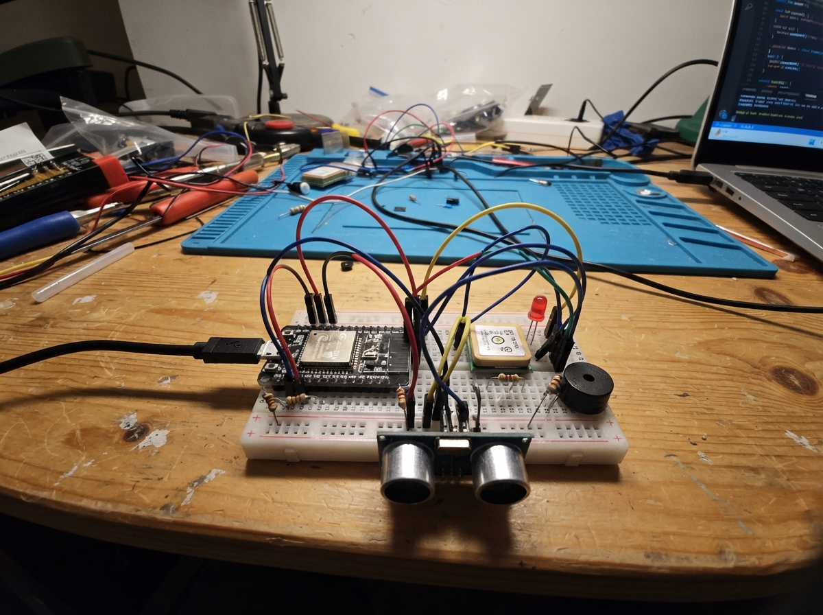
This ESP32 rescue beacon project combines GPS location tracking, ultrasonic distance sensing, and 2.4 GHz radio transmission to create a portable alert system. The device monitors nearby objects using the HC-SR04 sensor, acquires GPS coordinates via the L76X module, and broadcasts rescue data wirelessly using the NRF-HW237 radio. Visual and audio feedback from the LED and buzzer indicate system status and proximity alerts.
This guide provides a complete parts list, breadboard wiring diagram, and Arduino firmware to get the rescue beacon operational. Builders will learn how to integrate multiple sensors with the ESP32, handle serial communication for GPS data, configure SPI radio transmission, and implement real-time alert logic. The modular design makes it easy to test each subsystem before final assembly.
Wiring diagram

Gather all the parts
Assemble it in 6 steps
1. Place the ESP32 and make power rows
Push the ESP32 across the center gap of the breadboard so each side has its own holes. Plug the USB cable into the ESP32 and laptop. Run one wire from the ESP32 3V3 pin to a breadboard power row, one wire from 5V/VIN to a separate 5V row, and one wire from GND to a ground row.
- Use the labels printed on the board: G16 means GPIO16.
- Keep the 3V3 and 5V rows separate.
- Do not join the 3V3 row to the 5V row — 5 V can damage the GPS and radio.
2. Wire the GPS location module
Connect GPS VCC to the 3V3 row (power), GPS GND to the ground row (ground), GPS TX to ESP32 G16 (location data), and GPS RX to ESP32 G17 (setup data). Leave PPS empty.
- Take the model outdoors or beside a clear window for its first location fix.
- Make sure VCC and GND are not swapped — swapped power can damage the GPS module.
3. Add the distance sensor safely
Connect HC-SR04 VCC to the 5V row (power), GND to the ground row (ground), and TRIG to ESP32 G25 (distance-start signal). Connect HC-SR04 ECHO to one end of the 1 kΩ resistor. Join the other end of that 1 kΩ resistor to ESP32 G32 (safe returned signal) and to one end of the 2 kΩ resistor. Connect the free end of the 2 kΩ resistor to the ground row (ground).
- The joining point between both resistors and G32 is one shared breadboard row.
- Point the two round sensor eyes toward the area being checked.
- Do not connect HC-SR04 ECHO directly to G32 — its 5 V signal can damage the ESP32.
- Some standard HC-SR04 boards may not reliably detect the ESP32's 3.3 V TRIG signal; a 3.3 V-compatible HC-SR04P or a level converter is the reliable upgrade.
4. Add the light and sound alert
Connect ESP32 G26 to one end of the 220 Ω resistor (light control). Connect the resistor's other end to the LED long leg, then connect the LED short leg to the ground row (ground). Connect buzzer SIGNAL to ESP32 G33 (sound), and buzzer GND to the ground row (ground).
- The LED long leg is normally the positive leg.
- A quick close-object warning makes the LED flash and buzzer beep.
- Do not omit the 220 Ω resistor — it limits current so the LED and ESP32 output are protected.
5. Wire the rescue radio
Connect NRF-HW237 VCC to the 3V3 row (power), GND to the ground row (ground), CE to ESP32 G27 (radio control), CSN to ESP32 G4 (radio select), SCK to G18 (clock), MOSI to G23 (data sent), and MISO to G19 (data received). Leave IRQ empty.
- Keep these radio wires short and firmly pushed in.
- A second NRF-HW237 with matching receiver firmware is needed to receive the sent rescue message.
- Connect the radio to 3V3 only — 5 V can permanently damage it.
- Do not place the radio antenna directly against the ESP32 or metal objects; that reduces wireless range.
6. Check the rescue model before use
Check that every module uses the same ground row. Keep the HC-SR04 facing the search area, with the GPS antenna facing upward, and the radio antenna clear. The model sends distance, GPS status, and a rescue indication score once each second.
- The score is an indication: a nearby object gives 60 points, a valid GPS position gives 30, and a working radio gives 10.
- The HC-SR04 detects a nearby surface or movement; it cannot confirm that the surface is a person.
- Do not use this breadboard demonstration as the only safety system in a real disaster response.
Review all connections
1. Connections between "gps_l76x" and "ESP32"
2. Connections between "led_resistor" and "ESP32"
3. Connections between "alert_led" and "ESP32"
4. Connections between "buzzer_1" and "ESP32"
5. Connections between "hcsr04_1" and "ESP32"
6. Connections between "echo_resistor_2k" and "ESP32"
7. Connections between "echo_resistor_1k" and "ESP32"
8. Connections between "nrf_hw237_1" and "ESP32"
Deploy the firmware
#include <Arduino.h>
#include <SPI.h>
#include <RF24.h>
#include <TinyGPS++.h>
#include <NewPing.h>

// Use the labels printed on the ESP32: for example, G16 means GPIO16.

// Hoisted type definitions
struct RescueMessage {
  uint16_t distanceCm;
  uint8_t confidencePercent;
  uint8_t flags; // bit 0: nearby object, bit 1: GPS location valid
  int32_t latitudeE6;
  int32_t longitudeE6;
};


// Forward declarations
void readGps();
void updateDistance();
uint8_t rescueConfidence(bool gpsFix);
void startBeep(uint32_t now);
void updateBuzzer(uint32_t now, bool gpsFix);
void updateLed(uint32_t now, bool gpsFix);
void transmitRescueMessage(bool gpsFix);

constexpr uint8_t GPS_RX_PIN = 16;
constexpr uint8_t GPS_TX_PIN = 17;
constexpr uint8_t ULTRASONIC_TRIG_PIN = 25;
constexpr uint8_t ULTRASONIC_ECHO_PIN = 32;
constexpr uint8_t LED_PIN = 26;
constexpr uint8_t BUZZER_PIN = 33;
constexpr uint8_t RADIO_CE_PIN = 27;
constexpr uint8_t RADIO_CSN_PIN = 4;
constexpr uint8_t RADIO_SCK_PIN = 18;
constexpr uint8_t RADIO_MISO_PIN = 19;
constexpr uint8_t RADIO_MOSI_PIN = 23;

constexpr uint16_t MAX_DISTANCE_CM = 400;
constexpr uint16_t NEARBY_DISTANCE_CM = 100;
constexpr uint32_t DISTANCE_INTERVAL_MS = 250;
constexpr uint32_t RADIO_INTERVAL_MS = 1000;
constexpr uint32_t GPS_BLINK_INTERVAL_MS = 500;
constexpr uint32_t ALERT_BLINK_INTERVAL_MS = 125;
constexpr uint32_t BEEP_INTERVAL_MS = 300;
constexpr uint32_t BEEP_LENGTH_MS = 35;

const byte RADIO_ADDRESS[6] = "RSC01";


TinyGPSPlus gps;
HardwareSerial gpsSerial(2);
NewPing sonar(ULTRASONIC_TRIG_PIN, ULTRASONIC_ECHO_PIN, MAX_DISTANCE_CM);
RF24 radio(RADIO_CE_PIN, RADIO_CSN_PIN);

uint16_t distanceCm = 0;
bool objectNearby = false;
bool hadGpsFix = false;
bool radioReady = false;
bool buzzerOn = false;
uint32_t lastDistanceMs = 0;
uint32_t lastRadioMs = 0;
uint32_t lastBeepMs = 0;
uint32_t beepStartedMs = 0;

void readGps() {
  while (gpsSerial.available() > 0) {
    gps.encode(gpsSerial.read());
  }
}

void updateDistance() {
  distanceCm = sonar.ping_cm();
  objectNearby = distanceCm > 0 && distanceCm <= NEARBY_DISTANCE_CM;
}

uint8_t rescueConfidence(bool gpsFix) {
  // This is an indication for rescuers, not a human-identification result.
  uint8_t score = 0;
  if (objectNearby) score += 60;
  if (gpsFix) score += 30;
  if (radioReady) score += 10;
  return score;
}

void startBeep(uint32_t now) {
  digitalWrite(BUZZER_PIN, HIGH);
  buzzerOn = true;
  beepStartedMs = now;
}

void updateBuzzer(uint32_t now, bool gpsFix) {
  if (buzzerOn && now - beepStartedMs >= BEEP_LENGTH_MS) {
    digitalWrite(BUZZER_PIN, LOW);
    buzzerOn = false;
  }
  if (objectNearby && !buzzerOn && now - lastBeepMs >= BEEP_INTERVAL_MS) {
    lastBeepMs = now;
    startBeep(now);
  }
  if (gpsFix && !hadGpsFix && !buzzerOn) {
    startBeep(now);
  }
  hadGpsFix = gpsFix;
}

void updateLed(uint32_t now, bool gpsFix) {
  if (objectNearby) {
    digitalWrite(LED_PIN, ((now / ALERT_BLINK_INTERVAL_MS) % 2) == 0 ? HIGH : LOW);
  } else if (gpsFix) {
    digitalWrite(LED_PIN, HIGH);
  } else {
    digitalWrite(LED_PIN, ((now / GPS_BLINK_INTERVAL_MS) % 2) == 0 ? HIGH : LOW);
  }
}

void transmitRescueMessage(bool gpsFix) {
  if (!radioReady) return;

  RescueMessage message{};
  message.distanceCm = distanceCm;
  message.confidencePercent = rescueConfidence(gpsFix);
  message.flags = (objectNearby ? 0x01 : 0x00) | (gpsFix ? 0x02 : 0x00);
  if (gpsFix) {
    message.latitudeE6 = static_cast<int32_t>(gps.location.lat() * 1000000.0);
    message.longitudeE6 = static_cast<int32_t>(gps.location.lng() * 1000000.0);
  }

  radio.stopListening();
  const bool sent = radio.write(&message, sizeof(message));
  Serial.printf("Distance: %u cm | GPS: %s | rescue indication: %u%% | radio: %s\n",
                distanceCm, gpsFix ? "valid" : "searching", message.confidencePercent,
                sent ? "sent" : "no receiver acknowledgement");
}

void setup() {
  Serial.begin(115200);
  gpsSerial.begin(9600, SERIAL_8N1, GPS_RX_PIN, GPS_TX_PIN);
  pinMode(LED_PIN, OUTPUT);
  pinMode(BUZZER_PIN, OUTPUT);
  digitalWrite(LED_PIN, LOW);
  digitalWrite(BUZZER_PIN, LOW);

  SPI.begin(RADIO_SCK_PIN, RADIO_MISO_PIN, RADIO_MOSI_PIN, RADIO_CSN_PIN);
  radioReady = radio.begin();
  if (radioReady) {
    radio.setPALevel(RF24_PA_LOW);
    radio.setDataRate(RF24_250KBPS);
    radio.openWritingPipe(RADIO_ADDRESS);
    radio.stopListening();
  }
  Serial.println("Disaster-rescue indicator started.");
}

void loop() {
  const uint32_t now = millis();
  readGps();
  if (now - lastDistanceMs >= DISTANCE_INTERVAL_MS) {
    lastDistanceMs = now;
    updateDistance();
  }

  const bool gpsFix = gps.location.isValid();
  updateLed(now, gpsFix);
  updateBuzzer(now, gpsFix);

  if (now - lastRadioMs >= RADIO_INTERVAL_MS) {
    lastRadioMs = now;
    transmitRescueMessage(gpsFix);
  }
}
Remix this project
Make it yours in one click
Open a full copy of this project in your own Schematik workspace — diagram, code, parts, and assembly steps included. Swap the sensor, add features, or redesign the whole thing with AI. The author's original stays untouched.
Related projects

Create A Complete Electrical Schematic Esp32 Sma
ESP32 · September 17, 2026Ayansh Agrawal
ESP32 Kare Ekran Projeleri
ESP32 · September 16, 2026Seref Ai
Component Qty --------------------------- ------
ESP32 · September 16, 2026Yathartha Chakrawal