Community project
Create Me Good Schematic This Bread Board Setup
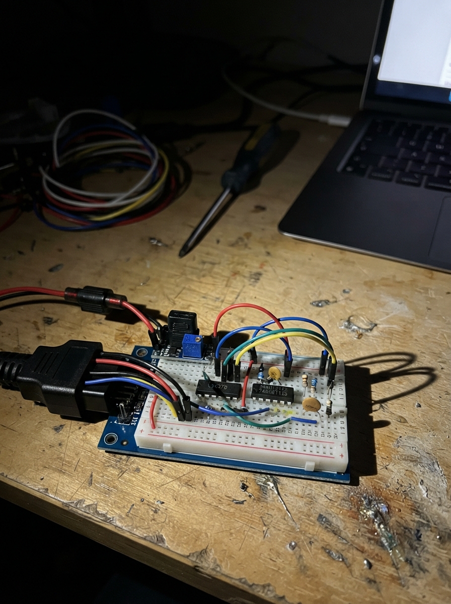
This guide builds an ESP32-based OBD-II K-line interface on a breadboard, enabling direct communication with vehicle diagnostic systems. The L9637D ISO 9141 transceiver handles the low-level K-line protocol while the 74AHCT125 level shifter safely converts between the ESP32's 3.3 V logic and the vehicle's 12 V bus. Protected by a 24 V buck converter, inline fuse, and signal diode, the circuit isolates the microcontroller from automotive electrical noise and transients.
This guide provides a complete wiring diagram, detailed parts list, step-by-step assembly instructions, and ready-to-use Arduino firmware that bridges USB serial to the vehicle K-line at 10,400 baud. Follow the assembly outline to build the power section first, establish the logic rails, wire the transceiver, add the receive-path voltage divider, and verify each stage before connecting to a live vehicle.
Wiring diagram

Gather all the parts
Assemble it in 7 steps
1. Place the two integrated circuits
Put the L9637D adapter or SO-8-to-DIP breakout across the breadboard’s centre gap. Put the 74AHCT125 DIP-14 across the centre gap as well, with its notch facing the same direction. Do not try to push a bare SO-8 L9637D directly into the breadboard.
- The tiny dot or notch marks pin 1 on each part; check it before wiring.
- Use an L9637D SO-8 breakout board or an L9637D K-line module if you do not want to solder the small IC.
- Putting either chip in the wrong direction can connect power to the wrong leg and damage it.
2. Make the protected vehicle-power section
Connect OBD-II pin 16 to the IN side of the 500 mA fuse. From the fuse OUT side, run one wire to the buck converter VIN+ and another to the unbanded end of the 1N4148 diode. Connect the buck converter VIN− to the ground rail. Before connecting the ESP32 or the chips, power this section from the car and adjust the buck converter until VOUT+ measures 5.0 V relative to VOUT−.
- Use a multimeter to set the converter to 5.0 V first.
- Keep the fuse close to the OBD pin-16 wire so a short in the breadboard is protected.
- Vehicle pin 16 is live battery power even with the ignition off; a wrong connection can damage the car wiring or the breadboard.
- Do not connect the 12 V OBD wire to any ESP32 pin or 3V3 pin.
3. Create the 5 V and ground rails
Run buck VOUT+ to the breadboard 5 V rail and buck VOUT− to the ground rail. Connect the ESP32 GND pin to that ground rail only. Connect L9637D pin 3 VCC and 74AHCT125 pin 14 VCC to the 5 V rail. Connect L9637D pin 5 GND and 74AHCT125 pin 7 GND to the ground rail. Do not connect the buck’s 5 V output to ESP32 3V3; use the ESP32 USB connector for its own power while testing.
- All grounds must join on the same ground rail so the data signals have a shared reference.
- The ESP32 is powered by USB for this breadboard setup; the vehicle supply only powers the interface circuit.
- Connecting 5 V to the ESP32 3V3 pin can permanently damage the ESP32.
4. Wire the K-line side
Connect the banded end of the 1N4148 diode to L9637D pin 7 VS. Put the 510 Ω resistor from that same VS point to L9637D pin 6 K. Put the 100 nF capacitor from VS to the ground rail. Connect OBD-II pin 7 directly to L9637D pin 6 K. Leave L9637D pin 2 LO and pin 8 LI unconnected because this build uses K-line only.
- The painted band on the 1N4148 faces the L9637D VS pin.
- Keep the 100 nF capacitor leads short; it helps keep vehicle electrical noise out of the chip.
- Do not connect OBD pin 7 directly to an ESP32 pin; K-line can rise to vehicle voltage and can destroy the ESP32.
5. Wire the ESP32 transmit path
Connect ESP32 GPIO17 to 74AHCT125 pin 2, labelled 1A. Connect 74AHCT125 pin 1, labelled 1OE, to ground so this buffer is always on. Connect 74AHCT125 pin 3, labelled 1Y, to L9637D pin 4 TX. This buffer changes the ESP32’s 3.3 V send signal into a dependable 5 V signal for the L9637D.
- On the DIP-14 chip, pin 1 is beside the notch; count counter-clockwise when looking down on the chip.
- GPIO17 → 1A (data), 1OE → GND (enable), 1Y → L9637D TX (data).
- Do not substitute a direct 5 V connection to GPIO17; ESP32 GPIO pins only accept 3.3 V signals.
6. Wire the ESP32 receive safety divider
Connect L9637D pin 1 RX to one end of the 10 kΩ resistor. Join its other end to ESP32 GPIO16. From that same GPIO16 junction, connect the 20 kΩ resistor to the ground rail. This divider reduces the L9637D’s 5 V receive output to about 3.3 V for the ESP32.
- L9637D RX → 10 kΩ → GPIO16 junction (data); GPIO16 junction → 20 kΩ → GND (ground).
- Keep the GPIO16 junction away from the 5 V rail.
- Connecting L9637D RX straight to GPIO16 can place 5 V on an ESP32 input and damage it.
7. Connect the OBD grounds and test in order
Connect both OBD-II pin 4 and pin 5 to the breadboard ground rail. Recheck that no OBD pin except 16, 4, 5, and 7 is connected. Then plug the ESP32 into USB, connect the OBD breakout to the vehicle only after checking the 5 V converter setting, and use Schematik’s Deploy button to flash the included serial bridge firmware.
- The intended OBD connections are pin 16 → fuse (power), pins 4 and 5 → GND (ground), and pin 7 → L9637D K (data).
- Many cars only answer K-line diagnostic requests when ignition is in the ON position; do not start the engine for bench testing.
- Never use this breadboard circuit while driving; loose wires can short or distract the driver.
- Do not probe or connect to OBD pins 6 and 14 in this project; those are CAN-bus pins, not the K-line used here.
Review all connections
1. Connections between "obd2_socket" and "ESP32"
2. Connections between "input_fuse" and "ESP32"
3. Connections between "buck_5v" and "ESP32"
4. Connections between "vs_diode" and "ESP32"
5. Connections between "k_pullup" and "ESP32"
6. Connections between "vs_capacitor" and "ESP32"
7. Connections between "kline_transceiver" and "ESP32"
8. Connections between "tx_buffer" and "ESP32"
9. Connections between "rx_bottom_resistor" and "ESP32"
10. Connections between "rx_top_resistor" and "ESP32"
Deploy the firmware
#include <Arduino.h>

// ESP32 UART2 connects to the L9637D K-line transceiver.
constexpr int KLINE_RX_PIN = 16;
constexpr int KLINE_TX_PIN = 17;
constexpr uint32_t KLINE_BAUD = 10400;

HardwareSerial KLine(2);

void setup() {
  Serial.begin(115200);
  KLine.begin(KLINE_BAUD, SERIAL_8N1, KLINE_RX_PIN, KLINE_TX_PIN);
  Serial.println();
  Serial.println("ESP32 K-line interface ready.");
  Serial.println("UART2: 10400 baud, RX GPIO16, TX GPIO17.");
}

void loop() {
  // This is a transparent bridge: bytes typed on USB serial are sent to K-line,
  // and bytes returned by the vehicle are printed on USB serial.
  while (Serial.available() > 0) {
    KLine.write(static_cast<uint8_t>(Serial.read()));
  }

  while (KLine.available() > 0) {
    Serial.write(static_cast<uint8_t>(KLine.read()));
  }
}
Remix this project
Make it yours in one click
Open a full copy of this project in your own Schematik workspace — diagram, code, parts, and assembly steps included. Swap the sensor, add features, or redesign the whole thing with AI. The author's original stays untouched.