Community project
Design Build Validate Low-cost Can-integrated Da
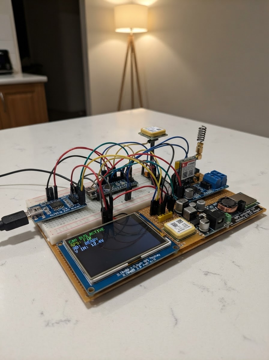
This guide builds a low-cost CAN bus data logger and display system for automotive projects, powered by an ESP32 microcontroller. The system reads vehicle CAN messages passively, displays real-time metrics on a 3.5-inch TFT screen, logs data to a microSD card, and transmits telemetry via GSM/GPRS. GPS positioning is captured alongside vehicle parameters like battery voltage, current, state of charge, motor and controller temperatures, RPM, and fault codes.
The guide provides a complete wiring diagram, bill of materials, firmware source code, and step-by-step assembly instructions. Learn how to integrate automotive-grade power protection, configure the MCP2515 CAN controller in listen-only mode, multiplex SPI peripherals, and set up UART communication with GPS and cellular modules. Bench testing procedures ensure reliable operation before vehicle installation.
Wiring diagram

Gather all the parts
Assemble it in 6 steps
1. Prepare protected power and enclosure
Mount the ESP32, CAN interface, GPS, SIM800L, microSD socket, TFT, and power-conditioning module in a sealed, vibration-resistant enclosure. Use locking connectors and strain relief; keep the GSM antenna and GPS antenna away from the motor controller and high-current traction wiring.
- Use an IP-rated enclosure with a clear UV-resistant display window.
- Use ferrules or crimp terminals rather than loose breadboard jumpers.
- Provide ventilation or thermal contact for the SIM800L and power converter.
- Disconnect the vehicle auxiliary supply before wiring.
- Do not route signal wiring alongside traction cables; cross them at right angles if unavoidable.
2. Wire the protected 12 V input and regulated rails
Connect WP5 protected 12 V auxiliary positive through a 2 A inline fuse to VIN12 of the power conditioner. Connect the WP5 low-voltage return to GND_IN. Feed ESP32 VIN and CAN-module VCC from protected 5 V; feed the 3.3 V TFT, GPS, and microSD modules from 3.3 V. Feed SIM800L only from the dedicated 4.0 V high-peak-current output and place a 1000 uF low-ESR capacitor across SIM800L VCC/GND at the modem.
- Power path: WP5 12 V → fuse → TVS/reverse-polarity power conditioner → 5 V / 3.3 V / 4.0 V rails.
- Use a short, thick SIM800L power pair and a star-like low-voltage ground return at the power conditioner.
- Verify rail voltages with a meter before connecting electronics.
- Never connect the 12 V auxiliary rail directly to the ESP32, TFT, GPS, SD module, CAN logic, or SIM800L.
- A SIM800L can draw current bursts near 2 A; the ESP32 3.3 V regulator cannot power it.
3. Wire the ESP32 shared SPI bus
Use the following diagram/net list. GPIO18 (SCK) fans out to TFT SCK, microSD SCK, and the 3.3 V-safe MCP2515 interface SCK. GPIO23 (MOSI) fans out to TFT MOSI, microSD MOSI, and CAN MOSI. GPIO19 (MISO) returns from microSD MISO and CAN MISO. Keep each chip-select separate: TFT CS GPIO25, SD CS GPIO13, CAN CS GPIO14. Wire TFT DC GPIO26, RESET GPIO33, and backlight LED GPIO32. Wire CAN INT to GPIO4.
- Diagram key: ESP32 GPIO18 ─┬─ TFT SCK ─┬─ SD SCK ─└─ CAN SCK; GPIO23 ─┬─ TFT MOSI ─┬─ SD MOSI ─└─ CAN MOSI; GPIO19 ←┬─ SD MISO ←└─ CAN MISO.
- The three SPI devices share clock/data wires but each has its own chip-select wire.
- Format and install the 16 GB microSD card before first use.
- Do not connect a 5 V MCP2515 MISO or INT output directly to ESP32 GPIO.
- Do not power a nominal 5 V ILI9488 or SD board from 3.3 V unless its label/datasheet explicitly permits it; use level shifting where required.
4. Connect GPS and GSM UARTs
Connect GPS TX to ESP32 GPIO16. Leave GPS RX unconnected unless module configuration is required. Connect SIM800L TX to ESP32 GPIO21 and ESP32 GPIO17 to SIM800L RX through a resistor divider or proper 3.3 V-to-2.8 V level shifter. Fit the specified antennas before powering either radio.
- UART diagram: NEO-6M TX → ESP32 GPIO16; SIM800L TX → ESP32 GPIO21; ESP32 GPIO17 → 2.8 V level shifter/divider → SIM800L RX.
- Place the GPS antenna with an unobstructed upward view and keep it away from the TFT and GSM antenna.
- Keep the SIM antenna outside a metal enclosure or use a suitable external antenna feed-through.
- Some NEO-6M breakouts transmit 5 V UART despite accepting 5 V power. Confirm 3.3 V TX or add a level shifter.
- Never transmit with the SIM800L without its antenna connected.
5. Attach the shared vehicle CAN bus as a passive node
With vehicle power off, connect CANH and CANL as a twisted pair to the matching shared WP CAN trunk. Connect the CAN reference/ground only according to the vehicle low-voltage grounding plan. The firmware configures the MCP2515 for 500 kbps listen-only mode, so it does not acknowledge or transmit frames.
- CAN diagram: WP shared CAN-H → CAN-module CANH; WP shared CAN-L → CAN-module CANL. Keep the pair twisted to the connector.
- Measure approximately 60 ohms between CANH and CANL with all vehicle power removed if the bus has two end terminators.
- Leave the CAN module's 120 ohm resistor disabled unless this dashboard is physically at a bus end.
- Never attach CANH/CANL to ESP32 GPIO pins.
- Do not add another terminator at a mid-bus node; it can degrade the bus and cause vehicle faults.
6. Bench-check before vehicle installation
Power from a fused bench 12 V source first. Verify 5 V, 3.3 V, and 4.0 V rails, then verify the TFT status screen, SD status, GPS fix indication, and CAN LIVE/STALE behavior. The firmware writes raw frames to canraw.csv and one trip record per second to trip.csv before any future GSM upload feature is enabled.
- Use the Deploy button in Schematik once the hardware checks are complete.
- Confirm the actual MCP2515 oscillator is 8 MHz; a 16 MHz board needs its firmware clock constant changed.
- The displayed decoded vehicle values use a documented provisional CAN map and provisional 5.12 kWh pack energy. Do not use the range display for operational decisions until WP6 supplies the approved DBC and pack usable-energy value.
- Secure the enclosure against vibration and recheck connector retention after a rough-road test.
Review all connections
1. Connections between "power_conditioner" and "ESP32"
2. Connections between "can_interface" and "ESP32"
3. Connections between "tft_display" and "ESP32"
4. Connections between "gps" and "ESP32"
5. Connections between "gsm" and "ESP32"
6. Connections between "sd_storage" and "ESP32"
7. Connections between "aux_12v" and "ESP32"
Deploy the firmware
#include <Arduino.h>
#include <SPI.h>
#include <SD.h>
#include <TinyGPS++.h>
#include <Arduino_GFX_Library.h>


struct CanFrame { uint32_t id; uint8_t dlc; uint8_t data[8]; };

struct Data{float v=NAN,a=NAN,soc=NAN,tBms=NAN,tMotor=NAN,tCtl=NAN;int rpm=0;uint16_t faults=0;uint8_t mode=0;bool interlock=false;uint32_t bmsAt=0;}d;


// Forward declarations
bool live();
void raw(const CanFrame&f);
void decode(const CanFrame&f);
void poll();
void logTrip();
void paint();

const uint16_t ID_BMS=0x180,ID_THERMAL=0x181,ID_VCU=0x280,ID_MOTOR=0x380;
const float USABLE_PACK_WH=5120.0f;
const int SD_CS=13,CAN_CS=14,CAN_INT=4,TFT_CS=25,TFT_DC=26,TFT_RST=33,TFT_BL=32,GPS_RX=16,GSM_RX=21,GSM_TX=17;


// Self-contained MCP2515 receive-only SPI driver: preserves physical CAN listen-only operation.
class Mcp2515ListenOnly {
 public:
  Mcp2515ListenOnly(int chipSelect,SPIClass &bus):cs(chipSelect),spi(bus){}
  bool begin500k8(){pinMode(cs,OUTPUT);digitalWrite(cs,HIGH);reset();delay(10);writeReg(0x2A,0x00);writeReg(0x29,0x90);writeReg(0x28,0x02);writeReg(0x2B,0x03);writeReg(0x0F,0x60);delay(2);return(readReg(0x0E)&0xE0)==0x60;}
  bool readMessage(CanFrame &f){uint8_t s=status();if(!(s&3))return false;select();spi.transfer((s&1)?0x90:0x94);uint8_t h=spi.transfer(0),l=spi.transfer(0),e8=spi.transfer(0),e0=spi.transfer(0);f.dlc=min((uint8_t)8,(uint8_t)(spi.transfer(0)&15));for(uint8_t i=0;i<f.dlc;i++)f.data[i]=spi.transfer(0);deselect();f.id=(l&8)?((uint32_t)h<<21)|((uint32_t)(l&0xE3)<<13)|((uint32_t)e8<<8)|e0:((uint16_t)h<<3)|(l>>5);modify(0x2C,(s&1)?1:2,0);return true;}
 private:
  int cs;SPIClass &spi;
  void select(){spi.beginTransaction(SPISettings(10000000,MSBFIRST,SPI_MODE0));digitalWrite(cs,LOW);}void deselect(){digitalWrite(cs,HIGH);spi.endTransaction();}
  void reset(){select();spi.transfer(0xC0);deselect();}uint8_t readReg(uint8_t r){select();spi.transfer(3);spi.transfer(r);uint8_t v=spi.transfer(0);deselect();return v;}void writeReg(uint8_t r,uint8_t v){select();spi.transfer(2);spi.transfer(r);spi.transfer(v);deselect();}void modify(uint8_t r,uint8_t m,uint8_t v){select();spi.transfer(5);spi.transfer(r);spi.transfer(m);spi.transfer(v);deselect();}uint8_t status(){select();spi.transfer(0xA0);uint8_t v=spi.transfer(0);deselect();return v;}
};

SPIClass spi(VSPI);Mcp2515ListenOnly can(CAN_CS,spi);TinyGPSPlus gps;HardwareSerial gpsPort(2),gsmPort(1);Arduino_DataBus *dbus=new Arduino_ESP32SPI(TFT_DC,TFT_CS,18,23,19,VSPI);
// The browser facade implements ILI9341 only; the ESP32 target retains the real ILI9488 driver.
#if defined(ARDUINO_ARCH_WASM) || defined(SCHEMATIK_WASM)
Arduino_GFX *tft=new Arduino_ILI9341(dbus,TFT_RST,1,false);
#else
Arduino_GFX *tft=new Arduino_ILI9488(dbus,TFT_RST,1,false);
#endif
bool sdOK=false,canOK=false;uint32_t lastLog=0,lastPaint=0,lastGpsByte=0;String prior="";
bool live(){return d.bmsAt&&millis()-d.bmsAt<1500;}int16_t i16(const uint8_t*x,int p){return(int16_t)(((uint16_t)x[p]<<8)|x[p+1]);}
void raw(const CanFrame&f){if(!sdOK)return;File q=SD.open("/canraw.csv",FILE_WRITE);if(!q)return;q.printf("%lu,%03lX,",(unsigned long)millis(),(unsigned long)(f.id&0x7FF));for(uint8_t i=0;i<f.dlc;i++){if(f.data[i]<16)q.print('0');q.print(f.data[i],HEX);}q.println();q.close();}
void decode(const CanFrame&f){uint16_t id=f.id&0x7FF;const uint8_t*x=f.data;if(id==ID_BMS&&f.dlc>=5){d.v=(((uint16_t)x[0]<<8)|x[1])*.1f;d.a=i16(x,2)*.1f;d.soc=x[4]*.5f;d.bmsAt=millis();}else if(id==ID_THERMAL&&f.dlc>=4){d.tBms=(int)x[0]-40;d.faults=((uint16_t)x[2]<<8)|x[3];}else if(id==ID_VCU&&f.dlc>=2){d.mode=x[0];d.interlock=x[1]&1;}else if(id==ID_MOTOR&&f.dlc>=4){d.rpm=i16(x,0);d.tCtl=(int)x[2]-40;d.tMotor=(int)x[3]-40;}}
void poll(){CanFrame f;while(canOK&&digitalRead(CAN_INT)==LOW&&can.readMessage(f)){raw(f);decode(f);}while(gpsPort.available()){lastGpsByte=millis();gps.encode(gpsPort.read());}}
void logTrip(){if(!sdOK)return;File q=SD.open("/trip.csv",FILE_WRITE);if(!q)return;bool fix=gps.location.isValid()&&lastGpsByte&&millis()-lastGpsByte<3000;q.printf("%lu,%.6f,%.6f,%.1f,%d,%.1f,%.1f,%.1f,%.0f,%d,%.1f,%.1f,%u,%u,%u\n",(unsigned long)millis(),fix?gps.location.lat():NAN,fix?gps.location.lng():NAN,gps.speed.isValid()?gps.speed.kmph():NAN,fix,d.v,d.a,d.soc,d.v*d.a,d.rpm,d.tBms,d.tMotor,d.faults,d.mode,d.interlock);q.close();}
void paint(){bool fix=gps.location.isValid()&&lastGpsByte&&millis()-lastGpsByte<3000;float range=!isnan(d.soc)?USABLE_PACK_WH*d.soc/100.0f/80.0f:NAN;String now=String(live())+String(fix)+String((int)(d.soc*10))+String((int)range)+String((int)d.a)+String(d.rpm)+String(d.faults);if(now==prior)return;prior=now;tft->fillScreen(0x0000);tft->setTextColor(0xFFFF);tft->setTextSize(2);tft->setCursor(10,10);tft->printf("TUK-TUK CAN:%s GPS:%s",live()?"LIVE":"STALE",fix?"FIX":"NO FIX");tft->setTextSize(4);tft->setCursor(12,60);tft->printf("SOC %5.1f%%",d.soc);tft->setCursor(12,110);tft->printf("RNG %4.0fkm",range);tft->setTextSize(2);tft->setCursor(12,175);tft->printf("PACK %.1fV %.1fA %.0fW",d.v,d.a,d.v*d.a);tft->setCursor(12,205);tft->printf("MOTOR %drpm M %.0fC C %.0fC",d.rpm,d.tMotor,d.tCtl);tft->setCursor(12,235);tft->printf("MODE %u INT %s FAULT %04X",d.mode,d.interlock?"OK":"OPEN",d.faults);tft->setCursor(12,280);tft->printf("SD:%s RAW+TRIP LOG",sdOK?"OK":"FAULT");}
void setup(){Serial.begin(115200);pinMode(TFT_BL,OUTPUT);digitalWrite(TFT_BL,HIGH);pinMode(CAN_INT,INPUT_PULLUP);spi.begin(18,19,23,CAN_CS);sdOK=SD.begin(SD_CS,spi)&&SD.cardType()!=0;if(sdOK&&!SD.exists("/trip.csv")){File q=SD.open("/trip.csv",FILE_WRITE);q.println("ms,lat,lon,gps_kph,gps_fix,pack_v,pack_a,soc,power_w,motor_rpm,bms_c,motor_c,faults,mode,interlock");q.close();}canOK=can.begin500k8();gpsPort.begin(9600,SERIAL_8N1,GPS_RX,-1);gsmPort.begin(9600,SERIAL_8N1,GSM_RX,GSM_TX);tft->begin();tft->fillScreen(0x0000);}
void loop(){poll();uint32_t n=millis();if(n-lastLog>=1000){lastLog=n;logTrip();}if(n-lastPaint>=500){lastPaint=n;paint();}}
Remix this project
Make it yours in one click
Open a full copy of this project in your own Schematik workspace — diagram, code, parts, and assembly steps included. Swap the sensor, add features, or redesign the whole thing with AI. The author's original stays untouched.
Related projects

Create A Complete Electrical Schematic Esp32 Sma
ESP32 · September 17, 2026Ayansh Agrawal
ESP32 Kare Ekran Projeleri
ESP32 · September 16, 2026Seref Ai
Component Qty --------------------------- ------
ESP32 · September 16, 2026Yathartha Chakrawal