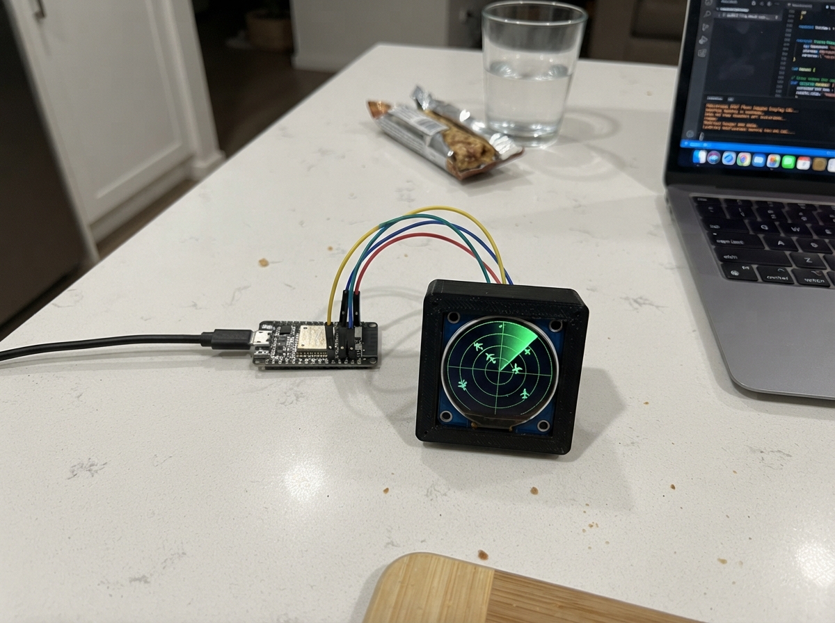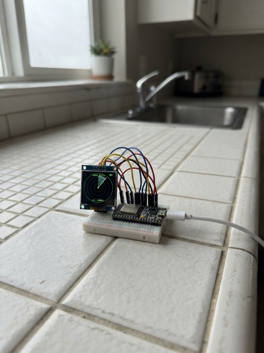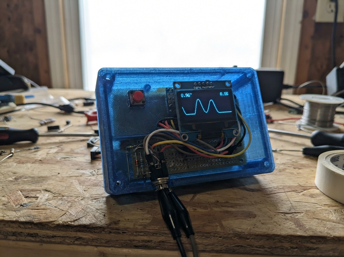
This project transforms an ESP32 into a basic digital oscilloscope and multimeter, capable of displaying real-time voltage waveforms on a compact OLED screen. The device uses a voltage divider and protection diodes to safely measure signals up to 10 volts, with adjustable time scales and measurement ranges controlled by three front-panel buttons.
Builders will receive a complete wiring diagram showing connections between the ESP32, OLED display, input protection circuit, and control buttons, along with a full parts list, Arduino firmware, and step-by-step assembly instructions. The guide covers safe construction of the protected probe input, proper button wiring, and initial testing procedures to verify measurements.
Wiring diagram
Gather all the parts
Assemble it in 6 steps
1. Place the board and screen
Put the ESP32 DevKit v1 and oled_1 on a breadboard or behind a small front panel. Keep the screen where it can be read like a meter display, with its printed pin labels visible.
- The OLED header order is printed on the board; do not rely on the left-to-right order used by a different-looking screen.
- Do not swap the OLED VCC and GND wires; swapped power can damage the screen.
2. Wire the screen
Connect oled_1 VCC to the ESP32 3V3 pin (power), oled_1 GND to an ESP32 GND pin (ground), oled_1 SDA to GPIO21 (data), and oled_1 SCL to GPIO22 (clock).
- Use short wires for the two screen signal wires so the display stays reliable.
3. Add the three front buttons
For range_button, connect one button leg to GPIO25 (signal) and the opposite leg to GND (ground). For time_button, connect one leg to GPIO26 (signal) and the opposite leg to GND (ground). For run_button, connect one leg to GPIO27 (signal) and the opposite leg to GND (ground).
- On a four-leg tactile switch, the two legs on one side are already joined inside. Use one leg from each opposite side; a quick tap will count exactly once.
- Do not connect these button signal legs to 3V3; the program already provides the gentle pull-up connection inside the ESP32.
4. Build the protected probe input
Connect probe_input SIG to input_divider VIN (signal), input_divider GND to ESP32 GND (ground), and input_divider OUT to GPIO34 (scaled signal). Build input_divider with a 100 kΩ resistor from VIN to OUT and a 33 kΩ resistor from OUT to GND; this makes the signal smaller before it reaches the ESP32.
- Label the input connector TIP and GND. The tip is the signal wire and the ground clip is the reference wire.
- Keep the divider and GPIO34 wire close together to reduce noise on the trace.
- Only connect low-voltage circuits whose ground is safe to join to the ESP32 ground. Never attach this input to a wall outlet, mains-powered appliance, or an unknown high-voltage source.
5. Add the input safety diodes
Connect positive_clamp_diode anode to the input_divider OUT and its striped cathode to 3V3 (positive clamp). Connect negative_clamp_diode striped cathode to input_divider OUT and its unstriped anode to GND (negative clamp).
- The painted band on each 1N4148 diode marks the cathode end. Check the bands before applying power.
- A diode installed backwards will not protect the ESP32 input. The divider and these diodes are not a safety rating for mains voltage.
6. Power and test safely
Before connecting a test signal, inspect that every GND wire joins the same ground rail and that GPIO34 only connects to input_divider OUT. Plug the ESP32 into USB for power, then use a known low-voltage source such as a battery or a 3.3 V signal generator.
- Start with the probe ground clip connected first, then touch the probe tip to the low-voltage signal.
Review all connections
1. Connections between "oled_1" and "ESP32"
2. Connections between "range_button" and "ESP32"
3. Connections between "time_button" and "ESP32"
4. Connections between "run_button" and "ESP32"
5. Connections between "probe_input" and "ESP32"
6. Connections between "input_divider" and "ESP32"
7. Connections between "positive_clamp_diode" and "ESP32"
8. Connections between "negative_clamp_diode" and "ESP32"
Deploy the firmware
#include <Wire.h>
#include <Adafruit_GFX.h>
#include <Adafruit_SSD1306.h>

#define OLED_SDA_PIN 21
#define OLED_SCL_PIN 22
#define ADC_PIN 34
#define RANGE_BUTTON_PIN 25
#define TIME_BUTTON_PIN 26
#define RUN_BUTTON_PIN 27

constexpr uint8_t SCREEN_WIDTH = 128;
constexpr uint8_t SCREEN_HEIGHT = 64;
constexpr uint8_t GRAPH_TOP = 17;
constexpr uint8_t GRAPH_BOTTOM = 57;
constexpr float ADC_REFERENCE_VOLTS = 3.30f;
constexpr float DIVIDER_RATIO = 4.03f;  // 100 kΩ / 33 kΩ divider
constexpr uint8_t TRACE_SAMPLES = 96;

Adafruit_SSD1306 display(SCREEN_WIDTH, SCREEN_HEIGHT, &Wire, -1);

const float fullScaleVolts[] = {3.3f, 10.0f};
const uint16_t sampleSpacingUs[] = {100, 500, 2000};
const char *timeLabels[] = {"0.1ms", "0.5ms", "2ms"};
uint16_t samples[TRACE_SAMPLES];
uint8_t rangeIndex = 1;
uint8_t timeIndex = 1;
bool running = true;
bool redrawNeeded = true;

bool buttonPressed(uint8_t pin) {
  static uint32_t lastPress[40] = {0};
  if (digitalRead(pin) == LOW && millis() - lastPress[pin] > 180) {
    lastPress[pin] = millis();
    return true;
  }
  return false;
}

float sampleToInputVolts(uint16_t raw) {
  return (static_cast<float>(raw) / 4095.0f) * ADC_REFERENCE_VOLTS * DIVIDER_RATIO;
}

void captureTrace() {
  const uint16_t spacing = sampleSpacingUs[timeIndex];
  for (uint8_t i = 0; i < TRACE_SAMPLES; ++i) {
    const uint32_t started = micros();
    samples[i] = analogRead(ADC_PIN);
    const uint32_t elapsed = micros() - started;
    if (elapsed < spacing) {
      delayMicroseconds(spacing - elapsed);
    }
  }
}

void drawScreen() {
  display.clearDisplay();
  display.setTextColor(SSD1306_WHITE);
  display.setTextSize(1);
  display.setCursor(0, 0);
  display.print(running ? "SCOPE  RUN" : "SCOPE  HOLD");
  display.setCursor(76, 0);
  display.print(fullScaleVolts[rangeIndex], 1);
  display.print("V");
  display.setCursor(0, 8);
  display.print("DIV ");
  display.print(timeLabels[timeIndex]);
  display.print("/pt");

  for (uint8_t y = GRAPH_TOP; y <= GRAPH_BOTTOM; y += 10) {
    display.drawFastHLine(0, y, SCREEN_WIDTH, SSD1306_WHITE);
  }
  for (uint8_t x = 0; x < SCREEN_WIDTH; x += 16) {
    display.drawFastVLine(x, GRAPH_TOP, GRAPH_BOTTOM - GRAPH_TOP + 1, SSD1306_WHITE);
  }

  const float scale = fullScaleVolts[rangeIndex];
  int previousX = 0;
  int previousY = GRAPH_BOTTOM;
  uint16_t peakRaw = 0;
  uint32_t sumRaw = 0;
  for (uint8_t i = 0; i < TRACE_SAMPLES; ++i) {
    const float volts = sampleToInputVolts(samples[i]);
    int y = GRAPH_BOTTOM - static_cast<int>((volts / scale) * (GRAPH_BOTTOM - GRAPH_TOP));
    y = constrain(y, GRAPH_TOP, GRAPH_BOTTOM);
    const int x = map(i, 0, TRACE_SAMPLES - 1, 0, SCREEN_WIDTH - 1);
    if (i > 0) {
      display.drawLine(previousX, previousY, x, y, SSD1306_WHITE);
    }
    previousX = x;
    previousY = y;
    sumRaw += samples[i];
    if (samples[i] > peakRaw) peakRaw = samples[i];
  }

  const float averageVolts = sampleToInputVolts(sumRaw / TRACE_SAMPLES);
  const float peakVolts = sampleToInputVolts(peakRaw);
  display.setCursor(0, 58);
  display.print("AVG:");
  display.print(averageVolts, 2);
  display.print(" P:");
  display.print(peakVolts, 2);
  display.display();
}

void setup() {
  pinMode(RANGE_BUTTON_PIN, INPUT_PULLUP);
  pinMode(TIME_BUTTON_PIN, INPUT_PULLUP);
  pinMode(RUN_BUTTON_PIN, INPUT_PULLUP);
  analogReadResolution(12);
  analogSetPinAttenuation(ADC_PIN, ADC_11db);
  Wire.begin(OLED_SDA_PIN, OLED_SCL_PIN);
  if (!display.begin(SSD1306_SWITCHCAPVCC, 0x3C)) {
    while (true) delay(1000);
  }
  display.clearDisplay();
  display.setTextColor(SSD1306_WHITE);
  display.setTextSize(1);
  display.setCursor(0, 20);
  display.println("Mini DMM Scope");
  display.println("Low-voltage input only");
  display.display();
  delay(900);
}

void loop() {
  if (buttonPressed(RANGE_BUTTON_PIN)) {
    rangeIndex = (rangeIndex + 1) % 2;
    redrawNeeded = true;
  }
  if (buttonPressed(TIME_BUTTON_PIN)) {
    timeIndex = (timeIndex + 1) % 3;
    redrawNeeded = true;
  }
  if (buttonPressed(RUN_BUTTON_PIN)) {
    running = !running;
    redrawNeeded = true;
  }

  if (running) {
    captureTrace();
    redrawNeeded = true;
  }
  if (redrawNeeded) {
    drawScreen();
    redrawNeeded = false;
  }
  delay(5);
}
Remix this project
Make it yours in one click
Open a full copy of this project in your own Schematik workspace, diagram, code, parts, and assembly steps included. Swap the sensor, add features, or redesign the whole thing with AI. The author's original stays untouched.