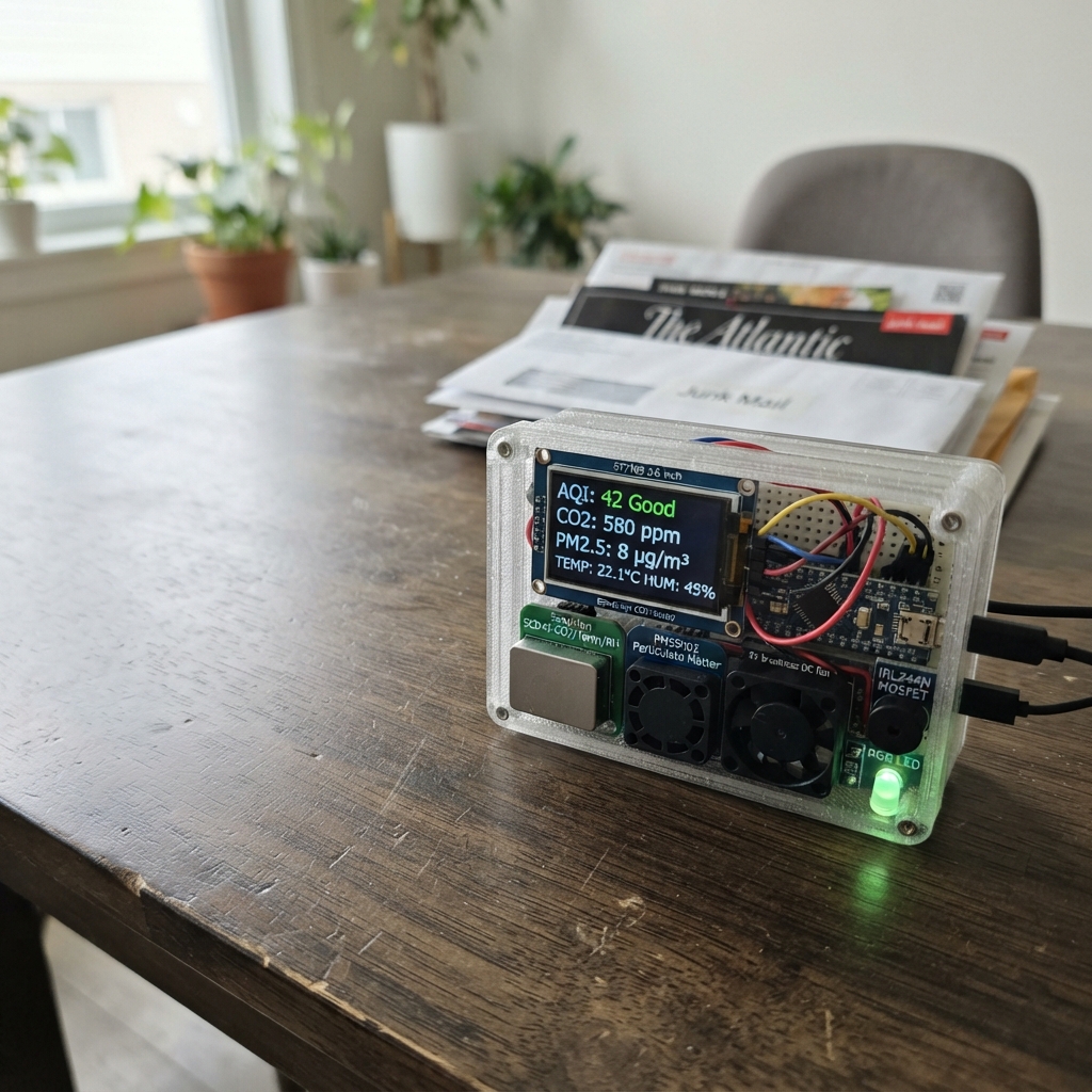
This desk air quality monitor continuously tracks CO2 levels, particulate matter, temperature, and humidity in your workspace. Built around an ESP32 microcontroller, it combines a Sensirion SCD40 CO2 sensor with a PMS5003 particulate matter sensor to provide real-time air quality data displayed on a 2-inch TFT screen, with optional data logging to microSD card.
The guide includes a complete wiring diagram, parts list, and step-by-step assembly instructions for integrating the sensors, display, fan control circuit, RGB status indicator, and alert system. You'll also get the Arduino firmware with WiFi connectivity, web interface, Telegram notifications, and configurable thresholds so the monitor can alert you when air quality degrades and automatically trigger ventilation.
Wiring diagram
Gather all the parts
Assemble it in 7 steps
1. Place the controller and power rails
Put the ESP32 DevKit on a breadboard or your two-layer PCB. Make one common ground rail and a 3.3 V rail; use the board’s 5 V/VIN rail only for the PMS5003 and fan. Power the finished station from the ESP32 USB socket.
- Use black wire for every GND connection, red wire for 5 V, and orange wire for 3.3 V so mistakes are easier to spot.
- Do not connect a separate 5 V supply unless its ground is also connected to the ESP32 ground; missing the shared ground makes signals unreliable.
2. Wire the CO2 sensor
Connect scd40_1 VCC to 3V3 (power), GND to GND (ground), SDA to GPIO21 (data), and SCL to GPIO22 (clock). Keep this small sensor away from the fan exhaust so it measures room air rather than a direct draft.
- The sensor needs several minutes after first power-up before its readings settle.
3. Wire the dust sensor
Connect pms5003_1 VCC to 5V (power), GND to GND (ground), TX to GPIO16 (sensor readings), and RX to GPIO17 (sensor control). Mount it so its two air openings are not blocked by the case.
- Use the supplied cable and adapter if your PMS5003 has the small white plug; do not force the plug backwards.
- The PMS5003 needs 5 V for its internal fan, but its TX and RX signal wires are 3.3 V logic; do not connect either signal wire to 5 V.
4. Wire the screen and card module
For tft_1, connect VCC to 3V3 (power), GND to GND (ground), SCK to GPIO18 (shared clock), MOSI to GPIO23 (shared data), CS to GPIO5 (screen select), DC to GPIO26 (screen command/data), and BL to 3V3 (backlight power). For sd_1, connect VCC to 3V3 (power), GND to GND (ground), SCK to GPIO18 (shared clock), MOSI to GPIO23 (shared data), MISO to GPIO19 (data from card), and CS to GPIO13 (card select).
- Format the microSD card as FAT32 before inserting it. The screen and card share three wires, but each has its own CS wire so they do not conflict.
- Make sure VCC and GND are not swapped on either module; swapped power can damage the screen or card module.
5. Build the fan switch
Connect fan_1 VCC to 5V (power) and fan_1 GND to mosfet_1 DRAIN (switched negative). Connect mosfet_1 SOURCE to GND (ground). Connect GPIO27 to r_gate P1 (fan-control signal), r_gate P2 to mosfet_1 GATE (signal), and connect r_gate_pull from that same GATE point to GND (keeps the fan off while the board starts). Put diode_fan_1 across the fan: its striped CATHODE end to 5V (protection) and its ANODE end to the fan negative/MOSFET DRAIN point (protection).
- For a bare TO-220 IRLZ44N facing you with its writing visible and legs downward, the usual leg order is Gate, Drain, Source; confirm the marking on your actual part before soldering.
- The stripe on the diode must face the 5 V fan wire. Reversing it makes a direct short when the fan turns on.
6. Add the light, buzzer, and buttons
Connect rgb_1 GND to GND (ground). Connect RGB red through r_red to GPIO25 (red status), green through r_green to GPIO32 (green status), and blue through r_blue to GPIO14 (blue status); each resistor is 220 Ω. Connect buzzer_1 SIG to GPIO33 (alert sound) and GND to GND (ground). Connect button_silence with one leg to GND and its other leg to GPIO4 (silence signal); connect r_button_silence_pull from 3V3 to that GPIO4/button point (keeps the input steady). Use the ESP32’s built-in BOOT button to change between live values and the graph.
- On the RGB LED, identify its common-cathode leg from the part’s flat edge or datasheet before soldering. A quick tap on the silence button mutes later sound alerts.
- Each RGB color needs its own 220 Ω resistor. Connecting an LED color straight to a GPIO can damage the LED or ESP32.
7. Finish the case and test the airflow
Fit the display in the front opening, keep the SCD40 exposed to room air, and give the PMS5003 a clear inlet and outlet. Mount fan_1 so it pushes air out of the case rather than directly blowing over the sensors. Insert the microSD card, then close the case without pinching the sensor cable.
- Before closing the case, plug in USB and check that the screen lights and the fan stays off while the air is good.
- Do not seal the sensor openings inside an airtight case; the station would then measure trapped case air instead of your room.
Review all connections
1. Connections between "scd40_1" and "ESP32"
2. Connections between "pms5003_1" and "ESP32"
3. Connections between "tft_1" and "ESP32"
4. Connections between "sd_1" and "ESP32"
5. Connections between "fan_1" and "ESP32"
6. Connections between "mosfet_1" and "ESP32"
7. Connections between "r_gate" and "ESP32"
8. Connections between "r_gate_pull" and "ESP32"
9. Connections between "buzzer_1" and "ESP32"
10. Connections between "rgb_1" and "ESP32"
11. Connections between "r_red" and "ESP32"
12. Connections between "r_green" and "ESP32"
13. Connections between "r_blue" and "ESP32"
14. Connections between "button_silence" and "ESP32"
15. Connections between "r_button_silence_pull" and "ESP32"
16. Connections between "diode_fan_1" and "ESP32"
Deploy the firmware
#include <Arduino.h>
#include <Wire.h>
#include <SPI.h>
#include <SD.h>
#include <WiFi.h>
#include <WebServer.h>
#include <WiFiClientSecure.h>
#include <time.h>
#include <SensirionI2cScd4x.h>
#include <Adafruit_PM25AQI.h>
#include <Adafruit_GFX.h>
#include <Adafruit_ST7789.h>
// Enter these only if you want the station to join your home Wi-Fi and use internet time/Telegram.
const char* WIFI_SSID = "";
const char* WIFI_PASSWORD = "";
const char* TELEGRAM_BOT_TOKEN = "";
const char* TELEGRAM_CHAT_ID = "";
const char* AP_NAME = "Study-Air-Station";
const char* AP_PASSWORD = "studyair2026";
const int SCD_SDA_PIN = 21;
const int SCD_SCL_PIN = 22;
const int PMS_RX_PIN = 16;
const int PMS_TX_PIN = 17;
const int TFT_CS_PIN = 5;
const int TFT_DC_PIN = 26;
const int SD_CS_PIN = 13;
const int SPI_SCK_PIN = 18;
const int SPI_MISO_PIN = 19;
const int SPI_MOSI_PIN = 23;
const int FAN_PIN = 27;
const int BUZZER_PIN = 33;
const int LED_R_PIN = 25;
const int LED_G_PIN = 32;
const int LED_B_PIN = 14;
const int SILENCE_PIN = 4;
const int PAGE_PIN = 0; // Onboard BOOT button, held low when pressed.
const uint8_t BUZZER_CHANNEL = 0;
const uint8_t RED_CHANNEL = 1;
const uint8_t GREEN_CHANNEL = 2;
const uint8_t BLUE_CHANNEL = 3;
const uint16_t CO2_WARN = 1000;
const uint16_t CO2_BAD = 1200;
const uint16_t PM25_WARN = 15;
const uint16_t PM25_BAD = 35;
const uint32_t SAMPLE_INTERVAL_MS = 5000;
const uint32_t LOG_INTERVAL_MS = 60000;
const uint32_t GRAPH_INTERVAL_MS = 300000;
SensirionI2cScd4x scd4x;
Adafruit_PM25AQI pms;
Adafruit_ST7789 tft(TFT_CS_PIN, TFT_DC_PIN, -1);
WebServer server(80);
struct Reading {
uint16_t co2 = 0;
float temperature = NAN;
float humidity = NAN;
uint16_t pm25 = 0;
uint16_t pm10 = 0;
bool scdOk = false;
bool pmsOk = false;
};
Reading reading;
uint16_t co2Trend[288];
uint16_t pmTrend[288];
uint16_t trendCount = 0;
uint16_t trendHead = 0;
uint8_t airLevel = 0; // 0 green, 1 yellow, 2 red
uint8_t page = 0;
bool sdReady = false;
bool alertSilenced = false;
bool lastSilenceState = HIGH;
bool lastPageState = HIGH;
uint32_t lastSample = 0;
uint32_t lastLog = 0;
uint32_t lastGraph = 0;
uint32_t lastTelegram = 0;
String timestampText() {
time_t now = time(nullptr);
if (now < 1700000000) return String("uptime_") + String(millis() / 1000);
struct tm timeInfo;
localtime_r(&now, &timeInfo);
char buffer[24];
strftime(buffer, sizeof(buffer), "%Y-%m-%d %H:%M:%S", &timeInfo);
return String(buffer);
}
String jsonReading() {
String out = "{\"time\":\"" + timestampText() + "\",\"co2\":" + String(reading.co2);
out += ",\"temperature\":" + String(reading.temperature, 1);
out += ",\"humidity\":" + String(reading.humidity, 1);
out += ",\"pm25\":" + String(reading.pm25) + ",\"pm10\":" + String(reading.pm10);
out += ",\"level\":" + String(airLevel) + ",\"sd\":" + String(sdReady ? "true" : "false") + "}";
return out;
}
void setRgb(uint8_t r, uint8_t g, uint8_t b) {
ledcWrite(LED_R_PIN, r); ledcWrite(LED_G_PIN, g); ledcWrite(LED_B_PIN, b);
}
void updateOutputs() {
bool bad = airLevel == 2;
digitalWrite(FAN_PIN, bad ? HIGH : LOW);
if (airLevel == 0) setRgb(0, 180, 0);
else if (airLevel == 1) setRgb(180, 100, 0);
else setRgb(200, 0, 0);
}
void beepAlert() {
if (!alertSilenced) {
ledcWriteTone(BUZZER_PIN, airLevel == 2 ? 2400 : 1600);
delay(120);
ledcWriteTone(BUZZER_PIN, 0);
}
}
void drawScreen();
void readSensors() {
bool changed = false;
bool dataReady = false;
uint16_t co2 = 0;
float temperature = NAN, humidity = NAN;
if (scd4x.getDataReadyStatus(dataReady) == 0 && dataReady &&
scd4x.readMeasurement(co2, temperature, humidity) == 0 && co2 > 0) {
changed |= reading.co2 != co2;
reading.co2 = co2;
reading.temperature = temperature;
reading.humidity = humidity;
reading.scdOk = true;
}
PM25_AQI_Data pmData;
if (pms.read(&pmData)) {
changed |= reading.pm25 != pmData.pm25_env || reading.pm10 != pmData.pm100_env;
reading.pm25 = pmData.pm25_env;
reading.pm10 = pmData.pm100_env;
reading.pmsOk = true;
}
uint8_t prior = airLevel;
if ((reading.scdOk && reading.co2 >= CO2_BAD) || (reading.pmsOk && reading.pm25 >= PM25_BAD)) airLevel = 2;
else if ((reading.scdOk && reading.co2 >= CO2_WARN) || (reading.pmsOk && reading.pm25 >= PM25_WARN)) airLevel = 1;
else airLevel = 0;
updateOutputs();
if (airLevel > prior) beepAlert();
if (changed || airLevel != prior) drawScreen();
}
void addTrendPoint() {
co2Trend[trendHead] = reading.co2;
pmTrend[trendHead] = reading.pm25;
trendHead = (trendHead + 1) % 288;
if (trendCount < 288) trendCount++;
}
uint16_t trendAt(uint16_t index) {
uint16_t first = (trendHead + 288 - trendCount) % 288;
return co2Trend[(first + index) % 288];
}
void drawHeader(uint16_t color, const char* label) {
tft.fillRect(0, 0, 320, 26, color);
tft.setTextColor(ST77XX_WHITE, color);
tft.setTextSize(2);
tft.setCursor(6, 5);
tft.print(label);
}
void drawScreen() {
uint16_t color = airLevel == 0 ? ST77XX_GREEN : (airLevel == 1 ? ST77XX_YELLOW : ST77XX_RED);
tft.fillScreen(ST77XX_BLACK);
drawHeader(color, airLevel == 0 ? "AIR: GOOD" : (airLevel == 1 ? "AIR: FAIR" : "OPEN WINDOW"));
tft.setTextSize(2);
tft.setTextColor(ST77XX_WHITE, ST77XX_BLACK);
if (page == 0) {
tft.setCursor(10, 42); tft.printf("CO2 %u ppm", reading.co2);
tft.setCursor(10, 72); tft.printf("PM2.5 %u ug/m3", reading.pm25);
tft.setCursor(10, 102); tft.printf("PM10 %u ug/m3", reading.pm10);
tft.setCursor(10, 142); tft.printf("Temp %.1f C", reading.temperature);
tft.setCursor(10, 172); tft.printf("Humidity %.0f%%", reading.humidity);
tft.setTextSize(1); tft.setCursor(10, 215);
tft.print(sdReady ? "Logging to microSD" : "microSD unavailable");
} else {
tft.setTextSize(1); tft.setCursor(8, 35); tft.print("CO2 24-hour trend (5 min points)");
tft.drawRect(8, 50, 304, 150, ST77XX_WHITE);
uint16_t maxValue = 1200;
for (uint16_t i = 0; i < trendCount; i++) if (trendAt(i) > maxValue) maxValue = trendAt(i);
if (maxValue < 600) maxValue = 600;
for (uint16_t i = 1; i < trendCount; i++) {
int x0 = 9 + (i - 1) * 302 / 287;
int x1 = 9 + i * 302 / 287;
int y0 = 198 - (int)((uint32_t)trendAt(i - 1) * 146 / maxValue);
int y1 = 198 - (int)((uint32_t)trendAt(i) * 146 / maxValue);
if (y0 < 51) y0 = 51; if (y1 < 51) y1 = 51;
tft.drawLine(x0, y0, x1, y1, ST77XX_CYAN);
}
tft.setCursor(10, 210); tft.printf("now %u ppm, scale %u", reading.co2, maxValue);
tft.setCursor(10, 225); tft.print("Press BOOT to return");
}
}
void appendLog() {
if (!sdReady) return;
File file = SD.open("/air.csv", FILE_APPEND);
if (!file) { sdReady = false; return; }
file.printf("%s,%u,%.1f,%.1f,%u,%u,%u\n", timestampText().c_str(), reading.co2,
reading.temperature, reading.humidity, reading.pm25, reading.pm10, airLevel);
file.close();
}
String urlEncode(const String& value) {
String out;
const char* hex = "0123456789ABCDEF";
for (size_t i = 0; i < value.length(); i++) {
char c = value[i];
if (isalnum(c)) out += c;
else if (c == ' ') out += '+';
else { out += '%'; out += hex[(c >> 4) & 15]; out += hex[c & 15]; }
}
return out;
}
void sendTelegramAlert() {
if (WiFi.status() != WL_CONNECTED || strlen(TELEGRAM_BOT_TOKEN) == 0 || strlen(TELEGRAM_CHAT_ID) == 0) return;
if (millis() - lastTelegram < 900000) return;
lastTelegram = millis();
String message = airLevel == 2 ? "Study Air Station: CO2 " + String(reading.co2) + " ppm, PM2.5 " + String(reading.pm25) + " ug/m3. Open a window."
: "Study Air Station: air quality is elevated. CO2 " + String(reading.co2) + " ppm.";
WiFiClientSecure client;
client.setInsecure();
if (client.connect("api.telegram.org", 443)) {
String path = "/bot" + String(TELEGRAM_BOT_TOKEN) + "/sendMessage?chat_id=" + String(TELEGRAM_CHAT_ID) + "&text=" + urlEncode(message);
client.print("GET " + path + " HTTP/1.1\r\nHost: api.telegram.org\r\nConnection: close\r\n\r\n");
client.stop();
}
}
void setupWeb() {
server.on("/", []() {
String html = "<!doctype html><html><meta name=viewport content='width=device-width'><style>body{font-family:sans-serif;background:#101820;color:#fff;margin:24px}.card{padding:18px;background:#1f2d36;border-radius:12px;max-width:420px}b{color:#66e0ff}</style><body><div class=card><h1>Study Air Station</h1><p>Refreshes every 10 seconds.</p><div id=d>Loading...</div></div><script>async function u(){let r=await fetch('/api');let x=await r.json();d.innerHTML='<p><b>'+x.time+'</b></p><p>CO2: '+x.co2+' ppm</p><p>PM2.5: '+x.pm25+' ug/m3 PM10: '+x.pm10+' ug/m3</p><p>Temperature: '+x.temperature+' C Humidity: '+x.humidity+'%</p><p>Air level: '+['good','fair','bad'][x.level]+'</p><p>microSD: '+(x.sd?'ready':'not ready')+'</p>'}u();setInterval(u,10000)</script></body></html>";
server.send(200, "text/html", html);
});
server.on("/api", []() { server.send(200, "application/json", jsonReading()); });
server.begin();
}
void setupNetwork() {
if (strlen(WIFI_SSID) > 0) {
WiFi.mode(WIFI_STA);
WiFi.begin(WIFI_SSID, WIFI_PASSWORD);
uint32_t started = millis();
while (WiFi.status() != WL_CONNECTED && millis() - started < 15000) delay(250);
}
if (WiFi.status() == WL_CONNECTED) configTime(0, 0, "pool.ntp.org", "time.nist.gov");
else { WiFi.mode(WIFI_AP); WiFi.softAP(AP_NAME, AP_PASSWORD); }
}
void setup() {
Serial.begin(115200);
pinMode(FAN_PIN, OUTPUT); digitalWrite(FAN_PIN, LOW);
pinMode(SILENCE_PIN, INPUT); // External 10 kOhm resistor holds this high.
pinMode(PAGE_PIN, INPUT_PULLUP);
ledcAttach(BUZZER_PIN, 2000, 8);
ledcAttach(LED_R_PIN, 5000, 8);
ledcAttach(LED_G_PIN, 5000, 8);
ledcAttach(LED_B_PIN, 5000, 8);
setRgb(0, 0, 0);
Wire.begin(SCD_SDA_PIN, SCD_SCL_PIN);
scd4x.begin(Wire, 0x62);
scd4x.stopPeriodicMeasurement(); delay(500);
scd4x.startPeriodicMeasurement();
Serial2.begin(9600, SERIAL_8N1, PMS_RX_PIN, PMS_TX_PIN);
pms.begin_UART(&Serial2);
SPI.begin(SPI_SCK_PIN, SPI_MISO_PIN, SPI_MOSI_PIN, SD_CS_PIN);
tft.init(240, 320); tft.setRotation(1); tft.fillScreen(ST77XX_BLACK);
sdReady = SD.begin(SD_CS_PIN);
if (sdReady && !SD.exists("/air.csv")) {
File file = SD.open("/air.csv", FILE_WRITE);
if (file) { file.println("timestamp,co2_ppm,temperature_c,humidity_pct,pm25_ugm3,pm10_ugm3,level"); file.close(); }
}
setupNetwork();
setupWeb();
drawScreen();
}
void loop() {
server.handleClient();
bool silenceNow = digitalRead(SILENCE_PIN);
bool pageNow = digitalRead(PAGE_PIN);
if (lastSilenceState == HIGH && silenceNow == LOW) { alertSilenced = true; drawScreen(); }
if (lastPageState == HIGH && pageNow == LOW) { page = 1 - page; drawScreen(); }
lastSilenceState = silenceNow;
lastPageState = pageNow;
uint32_t now = millis();
if (now - lastSample >= SAMPLE_INTERVAL_MS) { lastSample = now; readSensors(); if (airLevel > 0) sendTelegramAlert(); }
if (now - lastLog >= LOG_INTERVAL_MS) { lastLog = now; appendLog(); }
if (now - lastGraph >= GRAPH_INTERVAL_MS) { lastGraph = now; addTrendPoint(); if (page == 1) drawScreen(); }
delay(10);
}Remix this project
Make it yours in one click
Open a full copy of this project in your own Schematik workspace, diagram, code, parts, and assembly steps included. Swap the sensor, add features, or redesign the whole thing with AI. The author's original stays untouched.