Community project
Dual OLED Display Interface
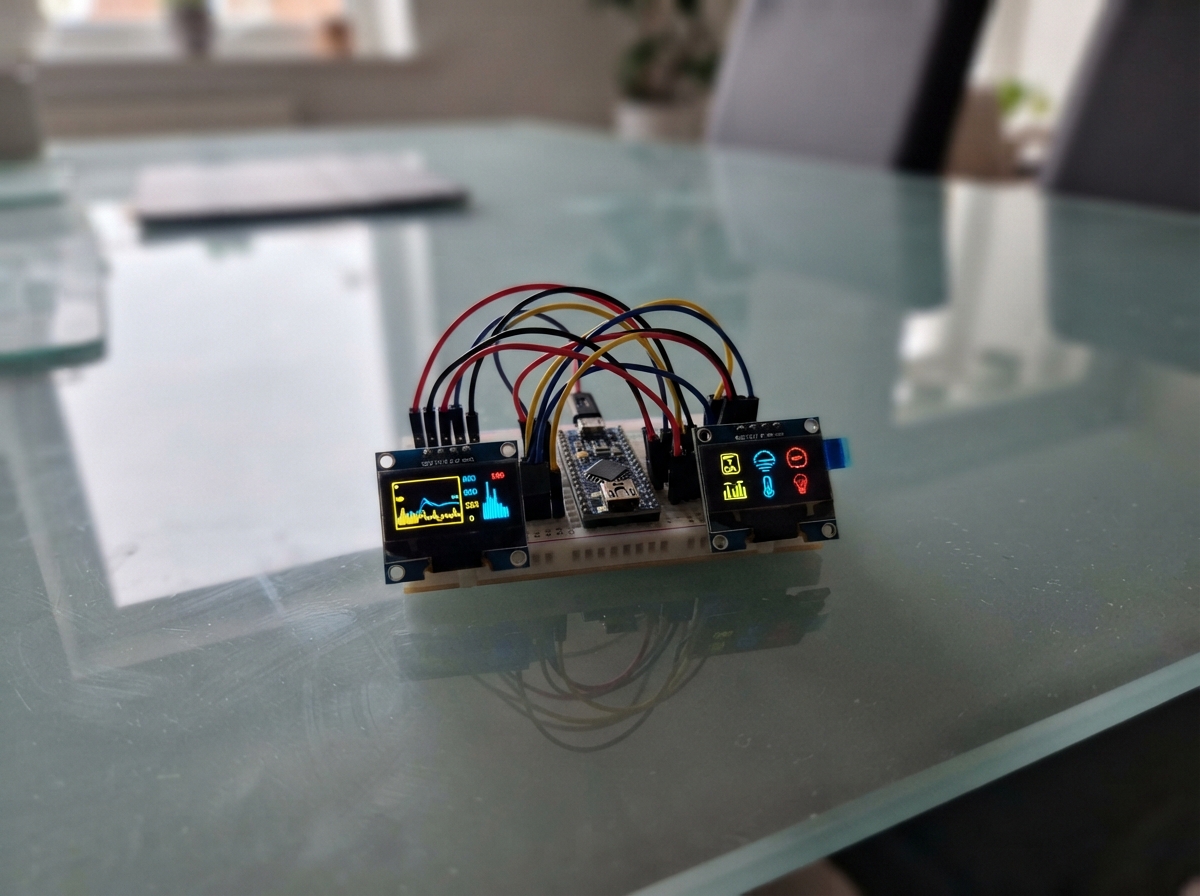
This project demonstrates how to control two independent SSD1331 OLED displays simultaneously using a single ESP32 microcontroller. Each 0.96-inch color display connects via SPI, sharing the clock and data lines while using separate chip select, data/command, and reset pins for independent control.
The guide provides a complete wiring diagram, parts list, and step-by-step assembly instructions to connect both displays safely. Included firmware initializes each screen and renders custom text and graphics, giving makers a foundation to build multi-display interfaces for dashboards, status monitors, or dual-panel applications.
Wiring diagram

Gather all the parts
Assemble it in 6 steps
1. Keep the power off while wiring
Leave the ESP32 unplugged from USB. Put the two SSD1331 modules beside the board and label them LEFT and RIGHT so their wires do not get mixed up.
- The pin labels are printed on the OLED module circuit board; match the printed labels rather than the pin position alone.
- Do not power either display from the ESP32 5V pin — these displays are wired here for 3.3V, and incorrect power can damage a screen.
2. Connect power to both screens
Connect LEFT VCC and RIGHT VCC to ESP32 3V3 (power). Connect LEFT GND and RIGHT GND to an ESP32 GND pin (ground). Both displays need the same ground connection as the ESP32.
- You can use one breadboard power row for 3V3 and a second row for GND, then run short jumpers to both displays.
- Make sure VCC and GND are not swapped — swapped power can damage the screens.
3. Connect the two shared signal wires
Connect LEFT SCL and RIGHT SCL to ESP32 GPIO18 (clock). Connect LEFT SDA and RIGHT SDA to ESP32 GPIO23 (data). These two wires are shared by both screens.
- Use the same breadboard row or a split jumper so each shared ESP32 pin reaches both display pins.
- Do not connect the modules' SCL or SDA pins to the ESP32 5V pin; they are signal wires, not power wires.
4. Connect the left screen control wires
Connect LEFT RES to GPIO16 (reset), LEFT DC to GPIO17 (command/data signal), and LEFT CS to GPIO25 (left-screen select). These wires make the ESP32 talk to the left screen separately.
- Keep these three wires grouped together and check each label before plugging in USB.
- A wire on the wrong CS, DC, or RES pin usually leaves the screen blank; recheck the printed module label and GPIO number.
5. Connect the right screen control wires
Connect RIGHT RES to GPIO4 (reset), RIGHT DC to GPIO13 (command/data signal), and RIGHT CS to GPIO26 (right-screen select). These are separate from the left screen's control wires.
- GPIO4, GPIO13, and GPIO26 are printed as numbers on most ESP32 DevKit v1 boards.
- Do not join the two CS pins together — each screen needs its own select wire so it can show different content.
6. Check then power the board
Check that both VCC wires go only to 3V3, both GND wires go only to GND, and that no loose jumper can touch a neighboring pin. Then plug the ESP32 into USB.
- After deployment, the left display shows a cyan frame and LEFT OLED, while the right display shows a magenta frame and RIGHT OLED.
- If either screen becomes hot, unplug USB immediately and inspect the VCC and GND wiring.
Review all connections
1. Connections between "ssd1331_left" and "ESP32"
2. Connections between "ssd1331_right" and "ESP32"
Deploy the firmware
#include <Arduino.h>
#include <Adafruit_GFX.h>
#include <Adafruit_SSD1331.h>


// Forward declarations
void drawScreen(Adafruit_SSD1331 &display, const char *title, uint16_t borderColour);

constexpr int OLED_SCLK = 18;
constexpr int OLED_MOSI = 23;
constexpr int LEFT_RST = 16;
constexpr int LEFT_DC = 17;
constexpr int LEFT_CS = 25;
constexpr int RIGHT_RST = 4;
constexpr int RIGHT_DC = 13;
constexpr int RIGHT_CS = 26;

// The displays share clock and data, but each has separate select, data/command, and reset wires.
Adafruit_SSD1331 leftDisplay(LEFT_CS, LEFT_DC, OLED_MOSI, OLED_SCLK, LEFT_RST);
Adafruit_SSD1331 rightDisplay(RIGHT_CS, RIGHT_DC, OLED_MOSI, OLED_SCLK, RIGHT_RST);

void drawScreen(Adafruit_SSD1331 &display, const char *title, uint16_t borderColour) {
  display.fillScreen(SSD1331_BLACK);
  display.drawRect(0, 0, 96, 64, borderColour);
  display.setTextWrap(false);
  display.setTextSize(1);
  display.setTextColor(borderColour);
  display.setCursor(8, 10);
  display.print(title);
  display.setTextColor(SSD1331_WHITE);
  display.setCursor(8, 30);
  display.print("SSD1331");
  display.setCursor(8, 43);
  display.print("Ready");
}

void setup() {
  leftDisplay.begin();
  rightDisplay.begin();
  drawScreen(leftDisplay, "LEFT OLED", SSD1331_CYAN);
  drawScreen(rightDisplay, "RIGHT OLED", SSD1331_MAGENTA);
}

void loop() {
  // Both screens are static, so no repeated redraw is needed.
}
Remix this project
Make it yours in one click
Open a full copy of this project in your own Schematik workspace — diagram, code, parts, and assembly steps included. Swap the sensor, add features, or redesign the whole thing with AI. The author's original stays untouched.
Related projects

Create A Complete Electrical Schematic Esp32 Sma
ESP32 · September 17, 2026Ayansh Agrawal
ESP32 Kare Ekran Projeleri
ESP32 · September 16, 2026Seref Ai
Component Qty --------------------------- ------
ESP32 · September 16, 2026Yathartha Chakrawal