Community project
Motorcycle Indicator Timeout Alert
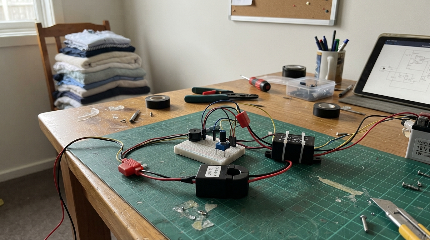
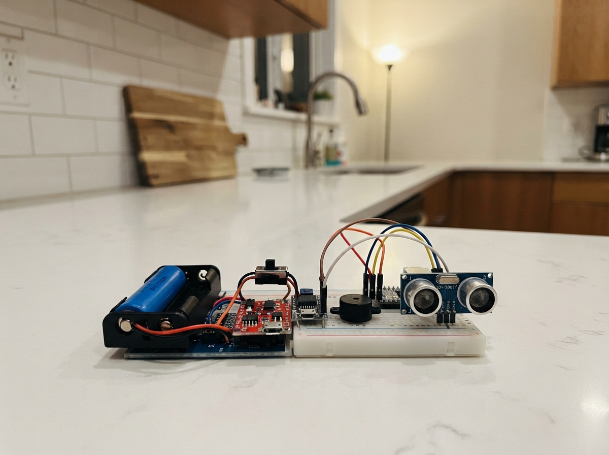
This project builds a safety device that alerts riders when their motorcycle turn signal has been left on too long. Using a clamp-on Hall effect current sensor, the Arduino detects when the indicator circuit is active and monitors how long it stays on. If the signal runs past a user-adjustable timeout (10 to 120 seconds), a buzzer sounds an intermittent alarm to remind the rider to cancel it.
The guide provides a complete wiring diagram, parts list, and step-by-step assembly instructions for mounting everything in a weatherproof enclosure. The firmware uses current sensing and timing logic to distinguish between normal indicator flashing and a forgotten signal. No cutting or splicing of motorcycle wiring is needed—the sensor simply clamps around the indicator wire.
Wiring diagram

Gather all the parts
Assemble it in 5 steps
1. Mount the parts in a protected box
Put the Arduino Nano, 5 V converter, clamp sensor, knob, and buzzer in a small waterproof or splash-resistant box. Leave the knob shaft and buzzer opening accessible, and position the clamp sensor so its clip can reach the selected indicator wire without stressing that wire.
- Use strain relief where every wire enters the box so vibration cannot pull a wire loose.
- Do not place the box near the exhaust, engine, steering movement, or a place where water can collect.
2. Make the protected 5 V power connection
Fit the 1 A fuse into the inline holder. Connect the motorcycle battery positive to the fuse holder battery side, then connect its protected side to VIN+ on the converter. Connect converter VIN− to battery negative or a clean chassis ground. Connect converter VOUT+ to the Nano 5V pin and VOUT− to Nano GND.
- Use the converter’s fixed 5 V output, not VIN, for the Nano power connection.
- Make sure VIN+ and VIN− are not swapped — reversed vehicle power can damage the converter and Arduino. Disconnect the motorcycle battery before making these connections.
3. Clip on the no-cut indicator sensor
Find one insulated wire that feeds only the chosen turn indicator lamp, then open the clamp sensor and close it around that one wire. Do not strip its insulation and do not put both the positive and return wires through the same clamp. Connect sensor VDD to Nano 5V (power), sensor GND to Nano GND (ground), and sensor VOUT to Nano A1 (signal).
- Confirm the chosen wire flashes only with the selected indicator. The sensor watches the changing current in that wire, rather than electrically touching the motorcycle circuit.
- Do not clamp around a complete two-wire cable containing both the outgoing and return wires — their magnetic fields cancel and the sensor will not detect the indicator. Keep all 12 V wiring out of the Nano pins.
4. Wire the timeout knob
Connect one outer knob terminal to Nano 5V (power), the other outer knob terminal to Nano GND (ground), and the middle knob terminal to Nano A0 (signal). Turning the knob sets the reminder delay from about 10 seconds at one end to 2 minutes at the other.
- If the delay runs backward from what you prefer, swap the two outer knob wires; the middle wire stays on A0.
- Do not connect the knob to the motorcycle 12 V wiring — it is a 5 V Nano control.
5. Connect the beeper and test safely
Connect the buzzer SIGNAL pin to Nano D9 (signal) and its GND pin to Nano GND (ground). Secure every connection, close the box, and test while the motorcycle is stationary: leave the indicator on past the knob-selected delay, then turn it off and confirm the beeping stops.
- If the sensor does not see an LED indicator, confirm its one-wire placement first; some very low-current LED indicators may need a more sensitive clamp sensor.
- Do not test while riding or let any loose wire reach the chain, wheel, exhaust, or steering stops.
Review all connections
1. Connections between "vehicle_battery" and "Arduino"
2. Connections between "power_fuse" and "Arduino"
3. Connections between "buck_5v" and "Arduino"
4. Connections between "timer_knob" and "Arduino"
5. Connections between "alarm_buzzer" and "Arduino"
6. Connections between "indicator_clamp_sensor" and "Arduino"
Deploy the firmware
#include <Arduino.h>

const uint8_t CLAMP_SENSOR_PIN = A1;
const uint8_t BUZZER_PIN = 9;
const uint8_t TIMER_KNOB_PIN = A0;

const unsigned long INDICATOR_GAP_MS = 1800UL;
const unsigned long MIN_DELAY_MS = 10000UL;
const unsigned long MAX_DELAY_MS = 120000UL;
const unsigned long BEEP_PERIOD_MS = 800UL;
const unsigned long BEEP_ON_MS = 200UL;

// The 10 A clamp sensor is centred near half the 5 V supply when no current flows.
// Averaging rejects small electrical noise from the motorcycle charging system.
const int ZERO_CURRENT_ADC = 512;
const int CURRENT_DETECT_DELTA = 4;

bool indicatorSessionActive = false;
unsigned long sessionStartedAt = 0;
unsigned long lastIndicatorPulseAt = 0;

int readClampSensor() {
  long total = 0;
  for (uint8_t i = 0; i < 16; ++i) {
    total += analogRead(CLAMP_SENSOR_PIN);
  }
  return total / 16;
}

bool indicatorCurrentIsFlowing() {
  const int reading = readClampSensor();
  return abs(reading - ZERO_CURRENT_ADC) >= CURRENT_DETECT_DELTA;
}

unsigned long selectedDelayMs() {
  const int knob = analogRead(TIMER_KNOB_PIN);
  return map(knob, 0, 1023, MIN_DELAY_MS, MAX_DELAY_MS);
}

void setup() {
  pinMode(BUZZER_PIN, OUTPUT);
  digitalWrite(BUZZER_PIN, LOW);
}

void loop() {
  const unsigned long now = millis();

  if (indicatorCurrentIsFlowing()) {
    lastIndicatorPulseAt = now;
    if (!indicatorSessionActive) {
      indicatorSessionActive = true;
      sessionStartedAt = now;
    }
  }

  // A normal flash has a short dark gap. A longer gap means the rider turned it off.
  if (indicatorSessionActive && (now - lastIndicatorPulseAt > INDICATOR_GAP_MS)) {
    indicatorSessionActive = false;
    digitalWrite(BUZZER_PIN, LOW);
    return;
  }

  if (!indicatorSessionActive || (now - sessionStartedAt < selectedDelayMs())) {
    digitalWrite(BUZZER_PIN, LOW);
    return;
  }

  // After the chosen delay, make a short beep every 0.8 seconds until the signal stops.
  const unsigned long beepPhase = (now - sessionStartedAt) % BEEP_PERIOD_MS;
  digitalWrite(BUZZER_PIN, beepPhase < BEEP_ON_MS ? HIGH : LOW);
}
Remix this project
Make it yours in one click
Open a full copy of this project in your own Schematik workspace — diagram, code, parts, and assembly steps included. Swap the sensor, add features, or redesign the whole thing with AI. The author's original stays untouched.