Community project
SmartCane Hazard Alerts
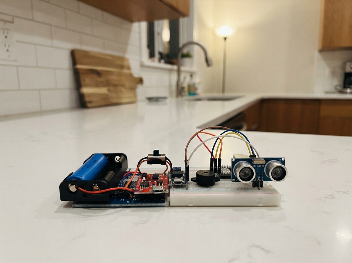
SmartCane Hazard Alerts is a mobility aid that uses three ultrasonic sensors to detect obstacles in front, at head height, and at ground level, alerting the user through audio and haptic feedback. Built around an Arduino Uno, the system combines a rechargeable 18650 battery pack, boost converter, and three distance sensors with an active buzzer and dual vibration motors to provide real-time proximity warnings.
This guide provides a complete parts list, wiring diagram, and step-by-step assembly instructions for building the SmartCane system. Readers will also receive the full Arduino firmware that manages sensor polling, obstacle detection logic, and alert coordination. The assembly process covers battery safety checks, power circuit construction, driver circuit layout on perfboard, sensor integration, and final waterproofing before mounting the electronics into the cane enclosure.
Wiring diagram

Gather all the parts
Assemble it in 7 steps
1. Check the battery parts before joining them
Use two matching protected 18650 cells of the same brand and capacity. Charge them separately until their voltages are within 0.1 V, then place them in the holder that is explicitly wired in parallel: positive-to-positive and negative-to-negative. Do not use a common two-cell holder unless you have confirmed it is parallel, because a series holder makes about 7.4 V and can damage the charger.
- Mark the holder “PARALLEL 1S” so it is not confused with a series holder later.
- Do not mix old and new cells or cells with different charge levels; a large equalizing current can overheat the cells.
2. Build and check the power section
With the switch open, wire the holder BAT+ to charger B+ and BAT− to charger B−. Wire charger OUT+ to the switch IN, switch OUT to boost VIN+, and charger OUT− to boost VIN−. Connect a USB-C charging lead only to the charger input pads. Before connecting the Nano or any sensors, turn the boost adjustment screw while measuring VOUT+ and VOUT− until it reads exactly 5.0 V.
- The charger must be the protected six-pad type so the load is taken from OUT+ and OUT−.
- Put the switch after the charger so the cells can still charge when the cane is off.
- Do not connect the 5 V rail to the Nano until the boost converter has been set to 5.0 V; a higher setting can damage the Nano and sensors.
3. Make the three driver circuits on perfboard
For each 2N2222, confirm its actual E-B-C pin order from its datasheet because TO-92 parts vary. Connect each emitter to the GND rail. Connect the buzzer transistor collector to buzzer −. Connect each motor transistor collector to that motor's − lead. Put one 1 kΩ resistor between D8 and the buzzer base, D9 and motor A base, and D10 and motor B base. Across each motor, fit a 1N4007 with its striped end on the motor + / 5 V side and its unstriped end on the motor − side.
- Keep the diode legs short and close to each motor connection.
- The buzzer’s marked or longer lead is + and goes to 5 V.
- A reversed motor diode will short the 5 V supply when the motor is turned on.
4. Connect the Nano and alert outputs
Run the boost VOUT+ line to the Nano 5V pin and the boost VOUT− line to Nano GND. Wire the buzzer + to 5 V and its − to the buzzer transistor collector. Wire each 5 V motor + to 5 V and its − to its own transistor collector. Keep every ground connection on the same GND rail.
- Use the Nano’s 5V pin, not VIN, because the boost converter is already regulated.
- Do not substitute 3 V coin motors for the specified 5 V-rated motors; 5 V can overheat or shorten the life of a 3 V motor.
5. Wire the three waterproof distance sensors
Keep each JSN-SR04T control board inside the enclosure and pass only its transducer cable through a cable gland. For every sensor, wire VCC → 5V (power) and GND → GND (ground). Wire front TRIG → D2 (signal) and ECHO → D3 (signal); head-level TRIG → D4 (signal) and ECHO → D5 (signal); ground TRIG → D6 (signal) and ECHO → D7 (signal).
- Use matching wire colours for each trigger/echo pair so they can be traced later.
- Leave the JSN-SR04T default mode pad unconnected.
- Make sure VCC and GND are not swapped — swapped power can damage a sensor board.
6. Bench-test before closing the enclosure
Place the cane at its normal angle above flat ground, switch it on, and keep it still for the first few seconds while the ground sensor calibrates. Two short beeps mean it is ready. Check a hand or flat board in front of each sensor: ground danger is one long alert, head danger is two quick alerts, and the front warning speeds up as the object comes closer.
- If ground alerts happen during normal walking, increase GROUND_TOLERANCE_CM in the firmware from 25 to 30 and deploy again.
- Test at walking speed in a clear indoor area first; this aid does not replace a white cane technique, orientation training, or supervision.
7. Mount and seal the cane
Mount the enclosure about 22–38 cm below the handle with its cable glands facing down. Put the head sensor near the enclosure aimed about 25° upward, the front transducer about 55 cm from the top aimed level, and the ground transducer about 70 cm from the top aimed about 25° downward. Put one vibration motor on each side inside the handle grip, then heat-shrink joints, tie the cable every 10 cm, and seal cable glands and openings with silicone.
- Start with a straight cane so the wires do not pass through folding joints.
- Leave the charging port accessible behind a rubber cover.
- Do not seal the buzzer completely airtight; it needs a protected sound opening to remain audible.
Review all connections
1. Connections between "cell_1" and "Arduino"
2. Connections between "cell_2" and "Arduino"
3. Connections between "battery_holder" and "Arduino"
4. Connections between "charger" and "Arduino"
5. Connections between "power_switch" and "Arduino"
6. Connections between "boost" and "Arduino"
7. Connections between "front_sensor" and "Arduino"
8. Connections between "head_sensor" and "Arduino"
9. Connections between "ground_sensor" and "Arduino"
10. Connections between "buzzer" and "Arduino"
11. Connections between "motor_a" and "Arduino"
12. Connections between "motor_b" and "Arduino"
13. Connections between "q_buzzer" and "Arduino"
14. Connections between "q_motor_a" and "Arduino"
15. Connections between "q_motor_b" and "Arduino"
16. Connections between "r_buzzer" and "Arduino"
17. Connections between "r_motor_a" and "Arduino"
18. Connections between "r_motor_b" and "Arduino"
19. Connections between "d_motor_a" and "Arduino"
20. Connections between "d_motor_b" and "Arduino"
Deploy the firmware
// SmartCane SC-01 Rev B
// Arduino Nano + three JSN-SR04T sensors, active buzzer, and two 5 V vibration motors.

const byte TRIG_FRONT = 2;
const byte ECHO_FRONT = 3;
const byte TRIG_HEAD = 4;
const byte ECHO_HEAD = 5;
const byte TRIG_GROUND = 6;
const byte ECHO_GROUND = 7;
const byte BUZZER_PIN = 8;
const byte MOTOR_A_PIN = 9;
const byte MOTOR_B_PIN = 10;

const int FRONT_MAX_CM = 200;
const int HEAD_MAX_CM = 150;
const int MIN_VALID_CM = 25;       // JSN-SR04T blind zone
const int GROUND_TOLERANCE_CM = 25;
const byte MOTOR_STRENGTH = 150;   // 0..255 PWM duty cycle
const unsigned long ECHO_TIMEOUT_US = 30000UL;

int groundBaseCm = 80;

long readCm(byte trigPin, byte echoPin) {
  digitalWrite(trigPin, LOW);
  delayMicroseconds(4);
  digitalWrite(trigPin, HIGH);
  delayMicroseconds(12);
  digitalWrite(trigPin, LOW);

  unsigned long echoUs = pulseIn(echoPin, HIGH, ECHO_TIMEOUT_US);
  if (echoUs == 0) return -1;
  return echoUs / 58L;
}

long readStableCm(byte trigPin, byte echoPin) {
  long samples[3];
  byte valid = 0;

  for (byte i = 0; i < 3; ++i) {
    long cm = readCm(trigPin, echoPin);
    if (cm >= MIN_VALID_CM) samples[valid++] = cm;
    delay(60); // prevents one ultrasonic ping from confusing the next one
  }

  if (valid == 0) return -1;
  if (valid == 1) return samples[0];
  if (valid == 2) return (samples[0] + samples[1]) / 2;

  if (samples[0] > samples[1]) { long t = samples[0]; samples[0] = samples[1]; samples[1] = t; }
  if (samples[1] > samples[2]) { long t = samples[1]; samples[1] = samples[2]; samples[2] = t; }
  if (samples[0] > samples[1]) { long t = samples[0]; samples[0] = samples[1]; samples[1] = t; }
  return samples[1];
}

void setAlerts(bool on) {
  digitalWrite(BUZZER_PIN, on ? HIGH : LOW);
  analogWrite(MOTOR_A_PIN, on ? MOTOR_STRENGTH : 0);
  analogWrite(MOTOR_B_PIN, on ? MOTOR_STRENGTH : 0);
}

void alert(byte pulses, int onMs, int offMs) {
  for (byte i = 0; i < pulses; ++i) {
    setAlerts(true);
    delay(onMs);
    setAlerts(false);
    if (i + 1 < pulses) delay(offMs);
  }
}

int calibrateGround() {
  long total = 0;
  byte count = 0;

  // Hold the cane normally over flat ground while this runs.
  for (byte i = 0; i < 12; ++i) {
    long cm = readCm(TRIG_GROUND, ECHO_GROUND);
    if (cm >= MIN_VALID_CM && cm <= 400) {
      total += cm;
      ++count;
    }
    delay(100);
  }

  return count ? total / count : groundBaseCm;
}

void setup() {
  pinMode(TRIG_FRONT, OUTPUT);
  pinMode(ECHO_FRONT, INPUT);
  pinMode(TRIG_HEAD, OUTPUT);
  pinMode(ECHO_HEAD, INPUT);
  pinMode(TRIG_GROUND, OUTPUT);
  pinMode(ECHO_GROUND, INPUT);
  pinMode(BUZZER_PIN, OUTPUT);
  pinMode(MOTOR_A_PIN, OUTPUT);
  pinMode(MOTOR_B_PIN, OUTPUT);

  digitalWrite(TRIG_FRONT, LOW);
  digitalWrite(TRIG_HEAD, LOW);
  digitalWrite(TRIG_GROUND, LOW);
  setAlerts(false);

  delay(1000);
  groundBaseCm = calibrateGround();
  alert(2, 100, 100); // ready: two short beeps and vibrations
}

void loop() {
  // Ground danger has priority: a sudden longer distance is a drop-off;
  // a sudden shorter distance is a low obstacle.
  long groundCm = readStableCm(TRIG_GROUND, ECHO_GROUND);
  if (groundCm < 0 || abs(groundCm - groundBaseCm) > GROUND_TOLERANCE_CM) {
    alert(1, 600, 0);
    delay(100);
    return;
  }

  long headCm = readStableCm(TRIG_HEAD, ECHO_HEAD);
  if (headCm >= MIN_VALID_CM && headCm <= HEAD_MAX_CM) {
    alert(2, 80, 80);
    delay(120);
    return;
  }

  long frontCm = readStableCm(TRIG_FRONT, ECHO_FRONT);
  if (frontCm >= MIN_VALID_CM && frontCm <= FRONT_MAX_CM) {
    int gapMs = map(frontCm, MIN_VALID_CM, FRONT_MAX_CM, 40, 600);
    alert(1, 60, gapMs);
    return;
  }

  delay(20);
}
Remix this project
Make it yours in one click
Open a full copy of this project in your own Schematik workspace — diagram, code, parts, and assembly steps included. Swap the sensor, add features, or redesign the whole thing with AI. The author's original stays untouched.