Community project
Offline Classroom Controller
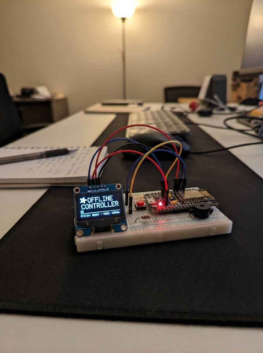
The Offline Classroom Controller is a standalone device that manages classroom sessions without requiring internet connectivity. Built around an Arduino Uno microcontroller with an SSD1327 OLED display, push buttons for navigation, status LEDs, and a buzzer for audio feedback, it provides a tactile interface for creating and monitoring classroom activities. An optional NodeMCU ESP8266 can be added for status synchronization when connectivity becomes available.
This guide includes a complete wiring diagram, detailed parts list, Arduino firmware with debounced button handling and QR code generation, and step-by-step assembly instructions. Builders will learn how to integrate the display via I2C, wire multiple control inputs with proper debouncing, manage visual and audio feedback through LEDs and a buzzer, and optionally connect wireless status reporting to extend the device's capabilities.
Wiring diagram

Gather all the parts
Assemble it in 7 steps
1. Prepare the enclosure and screen
Fit the 128×128 OLED module behind the black front window on four insulating standoffs, with its viewing area centered in the opening. Leave a small air gap so the glass does not press on the OLED panel.
- Use nylon standoffs or washers so metal screws cannot scratch the OLED circuit board.
- Do not overtighten the screen screws — pressure on the display glass can crack it.
2. Mount the controller boards
Lay the Arduino Uno flat on four brass or nylon posts inside the lower part of the case. Stand the NodeMCU upright behind it in two clips, leaving space above its antenna end and keeping it away from the metal enclosure wall.
- Keep the NodeMCU antenna end clear of large metal parts so a later wireless upgrade has the best chance of working.
- Do not let the bottom of either circuit board touch the metal-look enclosure — a short circuit can damage the boards.
3. Wire the display
Connect OLED VIN → Uno 5V (power), OLED GND → Uno GND (ground), OLED SDA → Uno A4 (data), and OLED SCL → Uno A5 (clock). Keep these four wires short and route them away from the buzzer.
- On the Uno, A4 and A5 are the two pins beside the analog inputs; they are used here as the screen wires.
- Make sure VIN and GND are not swapped — swapped power can damage the screen.
4. Fit and wire the rear controls
Install the four nearly flush rear switches in the order Nav, Select, Back, Session. Connect each switch's GND pin → Uno GND (ground). Connect Nav SIGNAL → D2 (signal), Select SIGNAL → D3 (signal), Back SIGNAL → D4 (signal), and Session SIGNAL → D5 (signal).
- These switches use the Uno's built-in pull-up setting, so each button needs only one signal wire and one ground wire.
- Do not connect a button signal pin to 5V — the firmware expects a button press to connect the signal pin to ground.
5. Install the lights and sounder
Place the green, yellow, and red LEDs in the front bezel from left to right. Connect each short LED leg → Uno GND (ground). Connect the long green leg → D6 through its 220 Ω series resistor (status signal), the long yellow leg → D7 through its 220 Ω series resistor (status signal), and the long red leg → D8 through its 220 Ω series resistor (status signal). Connect buzzer GND → Uno GND (ground) and buzzer SIGNAL → D9 (sound signal).
- The LED's longer leg is the positive leg; the resistor can go on either side of that LED, but it must remain in series with it.
- Never connect an LED straight to a Uno pin without its 220 Ω resistor — too much current can damage the LED or the Uno output pin.
6. Add the NodeMCU status link
Connect NodeMCU VIN → Uno 5V (power) and NodeMCU GND → Uno GND (ground). Build the small level-reducing link: Uno D10 → 1 kΩ resistor P1 (signal); 1 kΩ resistor P2 → NodeMCU RX (signal); at that same 1 kΩ P2 point connect the 2 kΩ resistor P1 (signal); connect 2 kΩ resistor P2 → GND (ground).
- The two resistor legs joining at the NodeMCU RX wire form a safe junction that reduces the Uno's 5V signal to about 3.3V.
- Do not wire Uno D10 straight to NodeMCU RX — 5V logic can damage the ESP8266 input.
7. Close the case and power Sntch
Tuck the wires into the cable-routing space, check that no wire is trapped by a panel edge, then close the front and rear plates. Power the Uno through its USB-B connector from a normal USB supply; the Uno's 5V rail powers the display and the hidden NodeMCU.
- Before closing the case fully, turn it on once: the face should appear and the OLED should be bright and readable.
- Only use a regulated USB 5V supply. If the enclosure is metal, make sure no bare wire can touch it.
Review all connections
1. Connections between "oled_128x128" and "Arduino"
2. Connections between "nav_button" and "Arduino"
3. Connections between "select_button" and "Arduino"
4. Connections between "back_button" and "Arduino"
5. Connections between "session_button" and "Arduino"
6. Connections between "status_green" and "Arduino"
7. Connections between "status_yellow" and "Arduino"
8. Connections between "status_red" and "Arduino"
9. Connections between "buzzer_5v" and "Arduino"
10. Connections between "nodemcu_esp8266" and "Arduino"
11. Connections between "uart_divider_top" and "Arduino"
12. Connections between "uart_divider_bottom" and "Arduino"
Deploy the firmware
#include <Arduino.h>
#include <Wire.h>
#include <U8g2lib.h>
extern "C" {
#include <qrcode.h>
}

const uint8_t NAV_PIN = 2;
const uint8_t SELECT_PIN = 3;
const uint8_t BACK_PIN = 4;
const uint8_t SESSION_PIN = 5;
const uint8_t GREEN_LED_PIN = 6;
const uint8_t YELLOW_LED_PIN = 7;
const uint8_t RED_LED_PIN = 8;
const uint8_t BUZZER_PIN = 9;
const uint8_t NODE_TX_PIN = 10;

U8G2_SSD1327_MIDAS_128X128_1_HW_I2C display(U8G2_R0, U8X8_PIN_NONE);

enum ScreenState { IDLE, CREATE_SESSION, CONFIGURE, GENERATE_QR, READY, ACTIVE, END_SESSION };
ScreenState state = IDLE;

struct Button { uint8_t pin; bool stable; bool lastReading; unsigned long changedAt; };
Button navButton = {NAV_PIN, HIGH, HIGH, 0};
Button selectButton = {SELECT_PIN, HIGH, HIGH, 0};
Button backButton = {BACK_PIN, HIGH, HIGH, 0};
Button sessionButton = {SESSION_PIN, HIGH, HIGH, 0};

uint8_t configItem = 0;
uint8_t roomNumber = 1;
uint8_t attendance = 0;
unsigned long activeStartedAt = 0;
unsigned long lastFaceFrameAt = 0;
uint8_t faceFrame = 0;
bool needsRedraw = true;

bool pressed(Button &button) {
  bool reading = digitalRead(button.pin);
  if (reading != button.lastReading) button.changedAt = millis();
  button.lastReading = reading;
  if ((millis() - button.changedAt) > 25 && reading != button.stable) {
    button.stable = reading;
    return button.stable == LOW;
  }
  return false;
}

void beep(uint16_t durationMs) { digitalWrite(BUZZER_PIN, HIGH); delay(durationMs); digitalWrite(BUZZER_PIN, LOW); }

void sendNodeByte(uint8_t value) {
  const uint16_t bitTime = 104;
  digitalWrite(NODE_TX_PIN, LOW); delayMicroseconds(bitTime);
  for (uint8_t bit = 0; bit < 8; bit++) { digitalWrite(NODE_TX_PIN, (value >> bit) & 1); delayMicroseconds(bitTime); }
  digitalWrite(NODE_TX_PIN, HIGH); delayMicroseconds(bitTime);
}

void sendNodeStatus() {
  const char *message = "IDLE\n";
  if (state == READY) message = "READY,SNTCH-4821\n";
  else if (state == ACTIVE) message = "ACTIVE,SNTCH-4821\n";
  else if (state == END_SESSION) message = "ENDED,SNTCH-4821\n";
  while (*message) sendNodeByte(*message++);
}

void setState(ScreenState next) {
  state = next;
  if (state == ACTIVE) activeStartedAt = millis();
  needsRedraw = true;
  sendNodeStatus();
}

void updateIndicators() {
  digitalWrite(GREEN_LED_PIN, state == READY || state == ACTIVE);
  digitalWrite(YELLOW_LED_PIN, state == CREATE_SESSION || state == CONFIGURE || state == GENERATE_QR);
  digitalWrite(RED_LED_PIN, state == END_SESSION);
}

void drawHeader(const char *title) {
  display.setFont(u8g2_font_5x8_tf);
  display.drawStr(5, 9, title);
  display.drawHLine(4, 12, 120);
}

void drawFace() {
  display.drawFrame(6, 6, 116, 116);
  display.setFont(u8g2_font_5x8_tf);
  display.drawStr(13, 21, "SNTCH  OFFLINE");
  int8_t look = (faceFrame == 3) ? -2 : (faceFrame == 4 ? 2 : 0);
  bool blink = (faceFrame == 1);
  if (blink) { display.drawHLine(38, 58, 10); display.drawHLine(80, 58, 10); }
  else if (faceFrame == 2) { display.drawCircle(43 + look, 58, 5); display.drawCircle(85 + look, 58, 5); }
  else { display.drawDisc(43 + look, 58, 4); display.drawDisc(85 + look, 58, 4); }
  display.drawLine(53, 83, 64, 85); display.drawLine(64, 85, 75, 82);
  display.setFont(u8g2_font_5x8_tf);
  display.drawStr(18, 108, "Press SESSION to begin");
}

void drawConfig() {
  drawHeader("CONFIGURE SESSION");
  display.setFont(u8g2_font_6x10_tf);
  char room[18]; snprintf(room, sizeof(room), "Room: %u", roomNumber);
  display.drawStr(18, 43, room); display.drawStr(18, 65, "Mode: Offline");
  display.setFont(u8g2_font_5x8_tf);
  display.drawStr(18, 90, "Nav: move  Select: change");
  display.drawFrame(10, configItem == 0 ? 30 : 52, 104, 18);
}

void drawQr() {
  drawHeader("JOIN THIS SESSION");
  QRCode qr;
  uint8_t qrData[64];
  qrcode_initText(&qr, qrData, 1, ECC_LOW, "SNTCH:4821");
  const uint8_t scale = 4, x0 = 22, y0 = 18;
  for (uint8_t y = 0; y < qr.size; y++) for (uint8_t x = 0; x < qr.size; x++)
    if (qrcode_getModule(&qr, x, y)) display.drawBox(x0 + x * scale, y0 + y * scale, scale, scale);
  display.setFont(u8g2_font_5x8_tf);
  display.drawStr(20, 112, "ID: SNTCH-4821  CODE: 4821");
}

void drawReady() {
  drawHeader("READY TO START");
  display.setFont(u8g2_font_6x10_tf);
  display.drawStr(24, 43, "Session ready"); display.drawStr(29, 63, "SNTCH-4821");
  display.drawStr(22, 90, "Press SESSION"); display.drawStr(32, 104, "to start");
}

void drawActive() {
  drawHeader("ACTIVE SESSION");
  unsigned long seconds = (millis() - activeStartedAt) / 1000UL;
  char timer[12], count[18];
  snprintf(timer, sizeof(timer), "%02lu:%02lu", seconds / 60UL, seconds % 60UL);
  snprintf(count, sizeof(count), "Present: %u", attendance);
  display.setFont(u8g2_font_logisoso24_tf); display.drawStr(24, 55, timer);
  display.setFont(u8g2_font_6x10_tf); display.drawStr(31, 82, count);
  display.setFont(u8g2_font_5x8_tf); display.drawStr(15, 108, "Select: +1   Session: end");
}

void drawEnd() {
  drawHeader("SESSION ENDED");
  char count[20]; snprintf(count, sizeof(count), "%u attendees saved", attendance);
  display.setFont(u8g2_font_6x10_tf);
  display.drawStr(30, 48, "All done."); display.drawStr(22, 72, count);
  display.setFont(u8g2_font_5x8_tf); display.drawStr(19, 106, "Back: home   Session: new");
}

void drawScreen() {
  display.firstPage();
  do {
    display.setDrawColor(0); display.drawBox(0, 0, 128, 128); display.setDrawColor(1);
    switch (state) {
      case IDLE: drawFace(); break;
      case CREATE_SESSION: drawHeader("CREATE SESSION"); display.setFont(u8g2_font_6x10_tf); display.drawStr(20, 53, "New local session"); display.drawStr(22, 86, "Press SESSION"); break;
      case CONFIGURE: drawConfig(); break;
      case GENERATE_QR: drawQr(); break;
      case READY: drawReady(); break;
      case ACTIVE: drawActive(); break;
      case END_SESSION: drawEnd(); break;
    }
  } while (display.nextPage());
}

void handleControls() {
  if (pressed(navButton)) { if (state == CONFIGURE) { configItem = (configItem + 1) % 2; needsRedraw = true; } beep(18); }
  if (pressed(selectButton)) {
    if (state == CONFIGURE && configItem == 0) { roomNumber = roomNumber % 9 + 1; needsRedraw = true; }
    else if (state == ACTIVE && attendance < 99) { attendance++; needsRedraw = true; }
    beep(25);
  }
  if (pressed(backButton)) {
    if (state == CREATE_SESSION) setState(IDLE); else if (state == CONFIGURE) setState(CREATE_SESSION);
    else if (state == GENERATE_QR) setState(CONFIGURE); else if (state == READY) setState(GENERATE_QR);
    else if (state == END_SESSION) setState(IDLE); beep(20);
  }
  if (pressed(sessionButton)) {
    if (state == IDLE || state == END_SESSION) { attendance = 0; setState(CREATE_SESSION); }
    else if (state == CREATE_SESSION) setState(CONFIGURE); else if (state == CONFIGURE) setState(GENERATE_QR);
    else if (state == GENERATE_QR) setState(READY); else if (state == READY) setState(ACTIVE);
    else if (state == ACTIVE) setState(END_SESSION); beep(55);
  }
}

void setup() {
  pinMode(NAV_PIN, INPUT_PULLUP); pinMode(SELECT_PIN, INPUT_PULLUP); pinMode(BACK_PIN, INPUT_PULLUP); pinMode(SESSION_PIN, INPUT_PULLUP);
  pinMode(GREEN_LED_PIN, OUTPUT); pinMode(YELLOW_LED_PIN, OUTPUT); pinMode(RED_LED_PIN, OUTPUT); pinMode(BUZZER_PIN, OUTPUT);
  pinMode(NODE_TX_PIN, OUTPUT); digitalWrite(NODE_TX_PIN, HIGH);
  Wire.begin(); display.begin(); updateIndicators(); drawScreen();
}

void loop() {
  handleControls(); updateIndicators();
  if (state == IDLE && millis() - lastFaceFrameAt >= 800) { lastFaceFrameAt = millis(); faceFrame = (faceFrame + 1) % 12; needsRedraw = true; }
  if (state == ACTIVE && millis() % 1000 < 25) needsRedraw = true;
  if (needsRedraw) { drawScreen(); needsRedraw = false; }
}
Remix this project
Make it yours in one click
Open a full copy of this project in your own Schematik workspace — diagram, code, parts, and assembly steps included. Swap the sensor, add features, or redesign the whole thing with AI. The author's original stays untouched.