Community project
ESP32 Chord Synthesizer
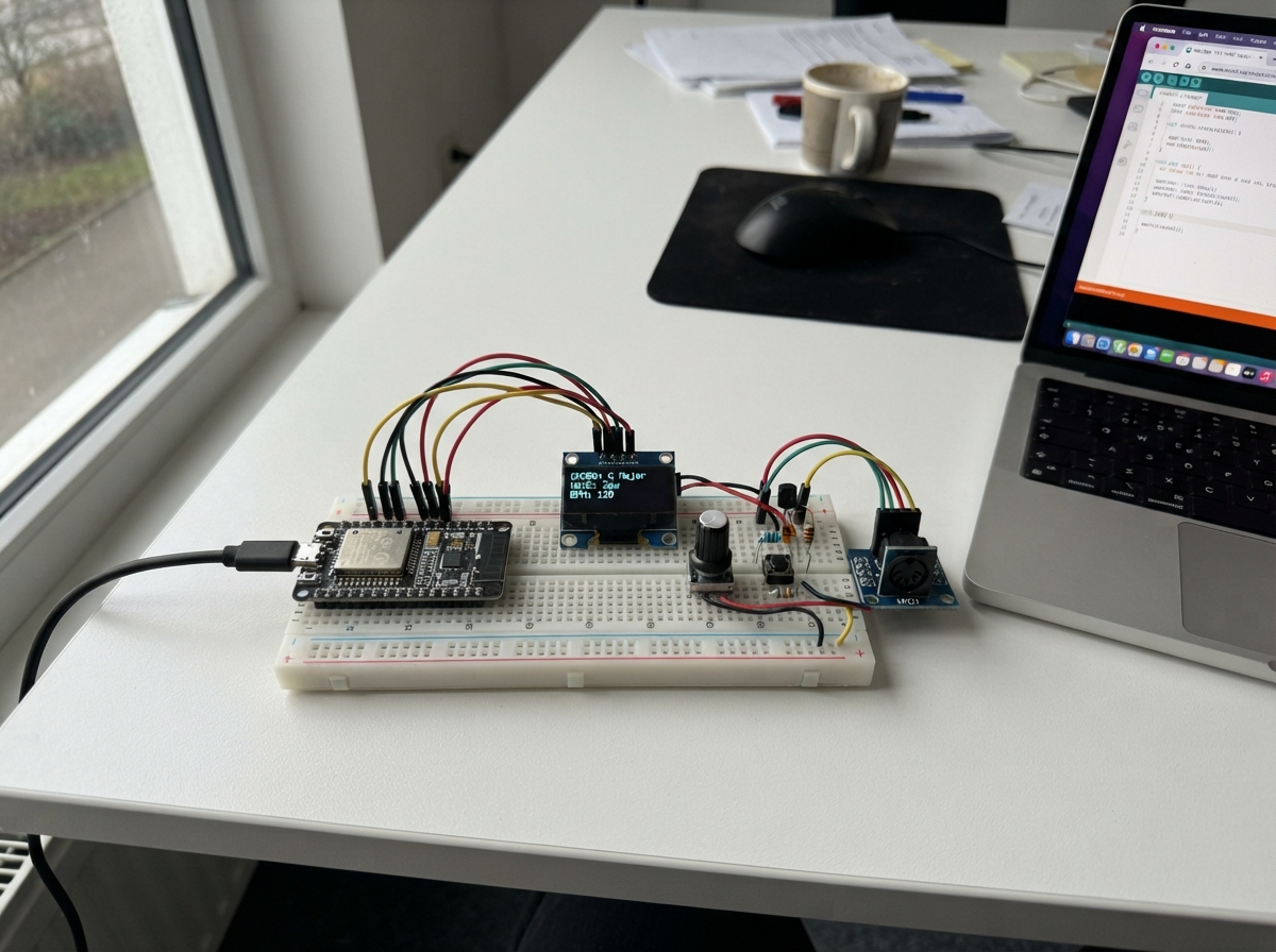
Build a MIDI synthesizer controller that generates chord progressions from seven buttons and a rotary encoder. This ESP32-based instrument displays the current key, chord quality, and scale degree on a small OLED screen, then sends the corresponding MIDI note data out through a standard 5-pin DIN connector to any MIDI-compatible synth or DAW.
The guide includes a complete wiring diagram showing how to connect the rotary encoder for octave and quality selection, seven chord buttons for scale degrees, and the MIDI output circuit built with a simple transistor switch. Assembly steps cover mounting the display and controls, wiring the button matrix, constructing the MIDI output stage, and uploading the firmware to get playing immediately.
Wiring diagram
Gather all the parts
Assemble it in 5 steps
1. Place the board and controls
Put the ESP32 DevKit v1, OLED screen, rotary encoder, seven momentary buttons, and the DIN socket on a breadboard or front panel. Label the buttons C, D, E, F, G, A, and B from left to right so the labels match the firmware.
- Keep the OLED label side facing you so you can read each printed pin name.
- Use separate rows for the four legs of each small push button; legs on the same side are already connected inside the button.
2. Wire the screen and knob
Connect OLED VCC to the ESP32 3V3 pin (power), OLED GND to ESP32 GND (ground), OLED SDA to GPIO21 (data), and OLED SCL to GPIO22 (clock). Connect the KY-040 encoder VCC to 3V3 (power), GND to GND (ground), CLK to GPIO32 (turning signal), DT to GPIO33 (turning signal), and SW to GPIO4 (knob-push signal).
- Some OLED boards print their header in a different physical order, so follow the printed VCC, GND, SDA, and SCL labels rather than the left-to-right order.
- Power the encoder from 3V3, not 5V, so its output signals stay safe for the ESP32.
3. Wire the seven chord buttons
For every chord button, connect one side to GND (ground). Connect the other side of C to GPIO13, D to GPIO14, E to GPIO16, F to GPIO17, G to GPIO25, A to GPIO26, and B to GPIO27 (button signals).
- All seven ground wires may join the same ground rail.
- The firmware supplies the small internal pull-up resistors, so each button needs only its signal wire and ground wire.
4. Build the MIDI output switch
With the flat face of a standard 2N3904 toward you, confirm its lead order is Emitter, Base, Collector from left to right. Connect the emitter to GND (ground). Connect GPIO18 to one end of the 1 kΩ resistor, then connect its other end to the transistor base (signal). Connect the transistor collector to one end of a 220 Ω resistor, then connect that resistor's other end to the DIN socket pin marked 5 (MIDI signal). Connect the ESP32 5V/VIN pin to one end of the other 220 Ω resistor, then connect its other end to DIN pin 4 (MIDI loop power).
- Use the tiny molded pin numbers on the DIN socket itself; they are more reliable than a drawing because the numbering looks mirrored when you turn the socket around.
- Only DIN pins 4 and 5 are used for this MIDI output. Leave pins 1, 2, and 3 unconnected.
5. Power it safely from USB
Before connecting USB, inspect the breadboard for a wire accidentally joining 3V3, 5V, and GND. Then plug the ESP32 into USB; USB powers the board, the OLED, and the MIDI output circuit.
- Do not connect the ESP32 3V3 pin to the 5V/VIN pin; that can damage the board.
- Do not swap OLED VCC and GND; swapped power can damage the screen.
- If the 2N3904 lead order does not match the marking on your particular transistor, use that part's datasheet instead; a wrong transistor orientation prevents MIDI output and may heat the part.
Review all connections
1. Connections between "oled" and "ESP32"
2. Connections between "encoder" and "ESP32"
3. Connections between "chord_c" and "ESP32"
4. Connections between "chord_d" and "ESP32"
5. Connections between "chord_e" and "ESP32"
6. Connections between "chord_f" and "ESP32"
7. Connections between "chord_g" and "ESP32"
8. Connections between "chord_a" and "ESP32"
9. Connections between "chord_b" and "ESP32"
10. Connections between "midi_base_r" and "ESP32"
11. Connections between "midi_q1" and "ESP32"
12. Connections between "midi_signal_r" and "ESP32"
13. Connections between "midi_vcc_r" and "ESP32"
Deploy the firmware
#include <Arduino.h>
#include <Wire.h>
#include <driver/uart.h>
#include <Adafruit_GFX.h>
#include <Adafruit_SSD1306.h>

constexpr int OLED_SDA_PIN = 21;
constexpr int OLED_SCL_PIN = 22;
constexpr int ENCODER_CLK_PIN = 32;
constexpr int ENCODER_DT_PIN = 33;
constexpr int ENCODER_SW_PIN = 4;
constexpr int CHORD_C_PIN = 13;
constexpr int CHORD_D_PIN = 14;
constexpr int CHORD_E_PIN = 16;
constexpr int CHORD_F_PIN = 17;
constexpr int CHORD_G_PIN = 25;
constexpr int CHORD_A_PIN = 26;
constexpr int CHORD_B_PIN = 27;
constexpr int MIDI_TX_PIN = 18;

constexpr uint8_t MIDI_CHANNEL = 0; // MIDI channel 1
constexpr uint8_t VELOCITY = 100;
constexpr uint8_t BASE_NOTE = 60;   // C4
constexpr uint32_t DEBOUNCE_MS = 18;

Adafruit_SSD1306 display(128, 64, &Wire, -1);
HardwareSerial MidiSerial(2);

const uint8_t chordPins[7] = {
  CHORD_C_PIN, CHORD_D_PIN, CHORD_E_PIN, CHORD_F_PIN,
  CHORD_G_PIN, CHORD_A_PIN, CHORD_B_PIN
};
const int8_t degreeSemitones[7] = {0, 2, 4, 5, 7, 9, 11};
const char* degreeNames[7] = {"I", "ii", "iii", "IV", "V", "vi", "vii"};
const char* keyNames[12] = {"C", "C#", "D", "D#", "E", "F", "F#", "G", "G#", "A", "A#", "B"};
const char* qualityNames[3] = {"Major", "Minor", "7th"};

bool stablePressed[7] = {false, false, false, false, false, false, false};
bool rawPressed[7] = {false, false, false, false, false, false, false};
uint32_t lastButtonChange[7] = {0, 0, 0, 0, 0, 0, 0};
int keyOffset = 0;
uint8_t quality = 0;
int lastEncoderClk = HIGH;
bool lastEncoderButton = HIGH;
uint32_t lastEncoderButtonChange = 0;
bool screenDirty = true;

void sendMidi(uint8_t status, uint8_t data1, uint8_t data2) {
  MidiSerial.write(status);
  MidiSerial.write(data1);
  MidiSerial.write(data2);
}

uint8_t chordRoot(uint8_t degree) {
  return BASE_NOTE + keyOffset + degreeSemitones[degree];
}

void sendChord(uint8_t degree, bool noteOn) {
  const uint8_t root = chordRoot(degree);
  int8_t intervals[4] = {0, 4, 7, -1};
  uint8_t count = 3;

  if (quality == 1) {
    intervals[1] = 3;
  } else if (quality == 2) {
    intervals[3] = 10;
    count = 4;
  }

  const uint8_t status = (noteOn ? 0x90 : 0x80) | MIDI_CHANNEL;
  const uint8_t velocity = noteOn ? VELOCITY : 0;
  for (uint8_t i = 0; i < count; ++i) {
    sendMidi(status, root + intervals[i], velocity);
  }
}

void stopAllNotes() {
  sendMidi(0xB0 | MIDI_CHANNEL, 123, 0);
}

void drawScreen() {
  display.clearDisplay();
  display.setTextColor(SSD1306_WHITE);
  display.setTextSize(1);
  display.setCursor(0, 0);
  display.println(F("HiChord Lite"));
  display.drawFastHLine(0, 11, 128, SSD1306_WHITE);

  display.setTextSize(2);
  display.setCursor(0, 18);
  display.print(keyNames[keyOffset]);
  display.setTextSize(1);
  display.setCursor(42, 24);
  display.print(qualityNames[quality]);

  display.setCursor(0, 47);
  display.print(F("Hold a chord button"));
  display.setCursor(0, 56);
  display.print(F("Knob: key  Press: type"));
  display.display();
  screenDirty = false;
}

void readEncoder() {
  const int encoderClk = digitalRead(ENCODER_CLK_PIN);
  if (encoderClk != lastEncoderClk && encoderClk == LOW) {
    if (digitalRead(ENCODER_DT_PIN) != encoderClk) {
      keyOffset = (keyOffset + 1) % 12;
    } else {
      keyOffset = (keyOffset + 11) % 12;
    }
    stopAllNotes();
    screenDirty = true;
  }
  lastEncoderClk = encoderClk;

  const bool encoderButton = digitalRead(ENCODER_SW_PIN);
  if (encoderButton != lastEncoderButton) {
    lastEncoderButtonChange = millis();
    lastEncoderButton = encoderButton;
  }
  if (!encoderButton && (millis() - lastEncoderButtonChange) == DEBOUNCE_MS) {
    quality = (quality + 1) % 3;
    stopAllNotes();
    screenDirty = true;
  }
}

void readChordButtons() {
  const uint32_t now = millis();
  for (uint8_t i = 0; i < 7; ++i) {
    const bool sample = digitalRead(chordPins[i]) == LOW;
    if (sample != rawPressed[i]) {
      rawPressed[i] = sample;
      lastButtonChange[i] = now;
    }
    if (sample != stablePressed[i] && now - lastButtonChange[i] >= DEBOUNCE_MS) {
      stablePressed[i] = sample;
      sendChord(i, sample);
      screenDirty = true;
    }
  }
}

void setup() {
  for (uint8_t i = 0; i < 7; ++i) {
    pinMode(chordPins[i], INPUT_PULLUP);
  }
  pinMode(ENCODER_CLK_PIN, INPUT_PULLUP);
  pinMode(ENCODER_DT_PIN, INPUT_PULLUP);
  pinMode(ENCODER_SW_PIN, INPUT_PULLUP);
  lastEncoderClk = digitalRead(ENCODER_CLK_PIN);

  // The NPN MIDI circuit inverts the electrical signal, so invert UART TX too.
  MidiSerial.begin(31250, SERIAL_8N1, -1, MIDI_TX_PIN);
  uart_set_line_inverse(UART_NUM_2, UART_SIGNAL_TXD_INV);

  Wire.begin(OLED_SDA_PIN, OLED_SCL_PIN);
  if (!display.begin(SSD1306_SWITCHCAPVCC, 0x3C)) {
    while (true) {
      delay(1000);
    }
  }
  drawScreen();
}

void loop() {
  readEncoder();
  readChordButtons();
  if (screenDirty) {
    drawScreen();
  }
  delay(2);
}
Remix this project
Make it yours in one click
Open a full copy of this project in your own Schematik workspace, diagram, code, parts, and assembly steps included. Swap the sensor, add features, or redesign the whole thing with AI. The author's original stays untouched.