Community project
ESP32 Cyberdeck Console
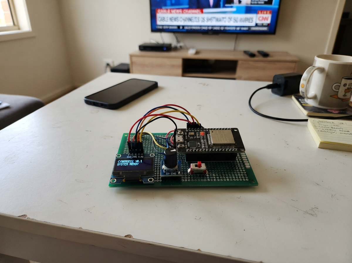
The ESP32 Cyberdeck Console is a compact retro-style interface built around an ESP32 microcontroller, a 128x64 OLED display, and a rotary encoder knob. It displays system information and terminal-like messages on a small monochrome screen, with menu navigation controlled by turning the encoder and pressing its button.
This guide provides a complete parts list, wiring diagram, and firmware to get the cyberdeck running. Assembly takes just a few minutes—mount the three modules, connect the display via I2C, wire up the encoder inputs, and verify all connections before powering on. The included Arduino sketch handles display rendering, encoder input with debouncing, and page navigation logic.
Wiring diagram

Gather all the parts
Assemble it in 4 steps
1. Place the three modules
Put the ESP32 DevKit v1, the small OLED screen, and the KY-040 knob module on a breadboard or non-conductive work surface. Leave room to reach the ESP32 USB socket and the knob shaft.
- Keep the labels on the OLED and knob module facing upward so each printed pin name is easy to read.
- Do not rest the powered board on metal; it can short the pins and damage the board.
2. Wire the small screen
Connect OLED VCC to the ESP32 3V3 pin (power), OLED GND to an ESP32 GND pin (ground), OLED SDA to GPIO21 (data), and OLED SCL to GPIO22 (clock).
- Use four different wire colors if possible; red for 3V3 and black for GND make mistakes easier to spot.
- Make sure VCC and GND are not swapped — swapped power can damage the screen.
3. Wire the control knob
Connect the KY-040 VCC pin to ESP32 3V3 (power), KY-040 GND to ESP32 GND (ground), KY-040 CLK to GPIO25 (turning signal), KY-040 DT to GPIO26 (turning direction signal), and KY-040 SW to GPIO27 (push signal).
- Powering this knob module from 3V3 keeps its signal wires safe for the ESP32's 3.3 V inputs.
- Do not connect the knob module VCC to 5V; its signal pins would then be too high for the ESP32.
4. Check before powering
Follow each wire from its printed module label to the named ESP32 pin one more time. Then plug the ESP32 into your computer with a data-capable USB cable; the USB cable supplies power to the board.
- If the screen remains blank after deployment, first check the four screen wires and confirm its VCC wire goes to 3V3.
- Unplug the USB cable before moving wires so an accidental short does not damage a module.
Review all connections
1. Connections between "oled_1" and "ESP32"
2. Connections between "encoder_1" and "ESP32"
Deploy the firmware
#include <Arduino.h>
#include <Wire.h>
#include <Adafruit_GFX.h>
#include <Adafruit_SSD1306.h>

constexpr int OLED_SDA_PIN = 21;
constexpr int OLED_SCL_PIN = 22;
constexpr int ENCODER_CLK_PIN = 25;
constexpr int ENCODER_DT_PIN = 26;
constexpr int ENCODER_SW_PIN = 27;
constexpr uint8_t OLED_ADDRESS = 0x3C;
constexpr int SCREEN_WIDTH = 128;
constexpr int SCREEN_HEIGHT = 64;
constexpr unsigned long DEBOUNCE_MS = 35;

Adafruit_SSD1306 display(SCREEN_WIDTH, SCREEN_HEIGHT, &Wire, -1);

uint8_t page = 0;
bool commandRan = false;
int lastClockState = HIGH;
int lastButtonState = HIGH;
unsigned long lastInputTime = 0;

void drawHeader(const char *title) {
  display.setTextColor(SSD1306_WHITE);
  display.setTextSize(1);
  display.setCursor(0, 0);
  display.print(F("[ CYBERDECK ]"));
  display.drawFastHLine(0, 10, SCREEN_WIDTH, SSD1306_WHITE);
  display.setCursor(0, 14);
  display.print(title);
}

void drawScreen() {
  display.clearDisplay();

  if (page == 0) {
    drawHeader("TERMINAL");
    display.setCursor(0, 28);
    display.print(F("> boot sequence ready"));
    display.setCursor(0, 40);
    display.print(commandRan ? F("> command accepted") : F("> press knob to run"));
    display.setCursor(0, 54);
    display.print(F("turn knob: pages"));
  } else if (page == 1) {
    drawHeader("SYSTEM");
    display.setCursor(0, 28);
    display.print(F("CPU: ESP32"));
    display.setCursor(0, 40);
    display.print(F("DISPLAY: ONLINE"));
    display.setCursor(0, 52);
    display.print(F("POWER: USB 5V"));
  } else {
    drawHeader("CONTROLS");
    display.setCursor(0, 28);
    display.print(F("TURN: change page"));
    display.setCursor(0, 40);
    display.print(F("PRESS: execute"));
    display.setCursor(0, 54);
    display.print(F("PAGE 3 / 3"));
  }

  display.display();
}

void handleEncoder() {
  int clockState = digitalRead(ENCODER_CLK_PIN);
  if (clockState != lastClockState && clockState == LOW) {
    if (digitalRead(ENCODER_DT_PIN) != clockState) {
      page = (page + 1) % 3;
    } else {
      page = (page + 2) % 3;
    }
    drawScreen();
  }
  lastClockState = clockState;
}

void handleButton() {
  int buttonState = digitalRead(ENCODER_SW_PIN);
  unsigned long now = millis();

  if (buttonState == LOW && lastButtonState == HIGH && now - lastInputTime > DEBOUNCE_MS) {
    lastInputTime = now;
    commandRan = !commandRan;
    drawScreen();
  }
  lastButtonState = buttonState;
}

void setup() {
  pinMode(ENCODER_CLK_PIN, INPUT_PULLUP);
  pinMode(ENCODER_DT_PIN, INPUT_PULLUP);
  pinMode(ENCODER_SW_PIN, INPUT_PULLUP);
  lastClockState = digitalRead(ENCODER_CLK_PIN);

  Wire.begin(OLED_SDA_PIN, OLED_SCL_PIN);
  if (!display.begin(SSD1306_SWITCHCAPVCC, OLED_ADDRESS)) {
    for (;;) {
      delay(1000);
    }
  }

  display.clearDisplay();
  display.setTextColor(SSD1306_WHITE);
  display.setTextSize(1);
  display.setCursor(18, 24);
  display.print(F("CYBERDECK READY"));
  display.display();
  delay(900);
  drawScreen();
}

void loop() {
  handleEncoder();
  handleButton();
}
Remix this project
Make it yours in one click
Open a full copy of this project in your own Schematik workspace — diagram, code, parts, and assembly steps included. Swap the sensor, add features, or redesign the whole thing with AI. The author's original stays untouched.