Community project
Zigbee Temperature Humidity Sensor
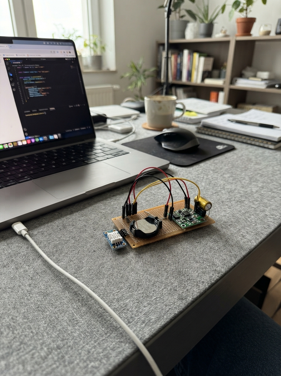
This project builds a battery-powered Zigbee temperature and humidity sensor using an ESP32-C6 microcontroller and a Sensirion SHTC3 sensor. The device wakes periodically to measure environmental conditions, reports them over Zigbee, then returns to deep sleep to maximize battery life from a single CR2450 coin cell.
The guide provides a complete wiring diagram, parts list, and step-by-step assembly instructions for integrating the power regulation circuit, supercapacitor burst-energy buffer, and sensor connections. Firmware code handles Zigbee network joining, sensor reading, and sleep scheduling to deliver updates every 15 minutes while consuming minimal power.
Wiring diagram

Gather all the parts
Assemble it in 5 steps
1. Prepare the coin-cell power section
Place the CR2450 holder and TPS63900 regulator module where their labels are visible. Solder the holder's BAT+ contact to the regulator VIN pin, and solder the holder's BAT- contact to a shared ground point. Leave the CR2450 cell out until the final step.
- Use short, thick wires for the two battery wires so the radio burst has the easiest path to the regulator.
- Do not connect the coin cell to the ESP32-C6-Zero 5V pin; that pin expects 5 V and the sensor must receive the regulator's 3.3 V output.
2. Add the burst-energy capacitor
Connect the supercapacitor's + lead to the same VIN point as the holder BAT+ wire, and connect its - lead to the same shared ground point as holder BAT-.
- On a polarized supercapacitor, the marked minus stripe is the - lead.
- Do not swap the capacitor leads — reversed polarity can overheat or permanently damage it.
3. Power the ESP32-C6-Zero safely
Connect TPS63900 VOUT to the ESP32-C6-Zero 3V3 pin (power), and connect TPS63900 GND to an ESP32-C6-Zero GND pin (ground). This bypasses the board's 5 V input path and gives the board the regulated 3.3 V it needs.
- For first programming, disconnect the battery supply and power the board only from USB. Do not use USB and the coin-cell supply together.
- Make sure the regulator output is 3.3 V before connecting it to the board — a higher voltage can damage the ESP32-C6-Zero.
4. Wire the temperature and humidity sensor
Connect SHTC3 VCC to the 3V3 point (power), SHTC3 GND to GND (ground), SHTC3 SDA to GPIO16 / TX header pin (data), and SHTC3 SCL to GPIO15 / SCL header pin (clock).
- Keep the sensor away from the ESP32-C6-Zero antenna and regulator so their warmth does not make the temperature reading look too high.
- Make sure VCC and GND are not swapped — swapped power can damage the sensor.
- Do not use the built-in RGB LED pin GPIO8 or the BOOT button pin GPIO9 for the sensor.
5. Program, join, and install the battery
With the coin cell still removed, plug the ESP32-C6-Zero into USB and use Deploy. Allow Zigbee joining on your coordinator, then reset the board so its first 10-second wake period can join. Once it appears as a temperature/humidity device, unplug USB and insert the CR2450 with its + face against the holder's + contact.
- The device wakes and sends a new reading about every 15 minutes; reset it while USB-powered if you need an immediate attempt to join.
- Never place a loose coin cell where a child or pet can reach it; swallowed coin cells are an emergency.
Review all connections
1. Connections between "cr2450_1" and "ESP32"
2. Connections between "cr2450_holder_1" and "ESP32"
3. Connections between "reservoir_cap_1" and "ESP32"
4. Connections between "tps63900_1" and "ESP32"
5. Connections between "shtc3_1" and "ESP32"
Deploy the firmware
#include <Arduino.h>
#include <Wire.h>
#include <Adafruit_SHTC3.h>
#include <Zigbee.h>
#include <esp_sleep.h>

constexpr int SHTC3_SDA_PIN = 16;
constexpr int SHTC3_SCL_PIN = 15;
constexpr uint8_t SENSOR_ENDPOINT = 10;
constexpr uint32_t SLEEP_SECONDS = 900;       // Send one update every 15 minutes.
constexpr uint32_t JOIN_TIMEOUT_MS = 10000;   // Avoid draining the cell if no Zigbee network is open.

Adafruit_SHTC3 shtc3;
ZigbeeTempSensor zigbeeSensor(SENSOR_ENDPOINT);

void sleepForNextReport() {
  Serial.println("Sleeping until the next report.");
  Serial.flush();
  esp_sleep_enable_timer_wakeup(static_cast<uint64_t>(SLEEP_SECONDS) * 1000000ULL);
  esp_deep_sleep_start();
}

bool joinZigbeeNetwork() {
  Zigbee.setTimeout(JOIN_TIMEOUT_MS);
  zigbeeSensor.addHumiditySensor(0.0f, 100.0f, 1.0f, 0.0f);
  Zigbee.addEndpoint(&zigbeeSensor);

  if (!Zigbee.begin()) {
    Serial.println("Zigbee could not start.");
    return false;
  }

  const uint32_t startedAt = millis();
  while (!Zigbee.connected() && millis() - startedAt < JOIN_TIMEOUT_MS) {
    delay(100);
  }
  return Zigbee.connected();
}

bool readAndReport() {
  sensors_event_t humidityEvent;
  sensors_event_t temperatureEvent;
  if (!shtc3.getEvent(&humidityEvent, &temperatureEvent)) {
    Serial.println("SHTC3 measurement failed.");
    return false;
  }

  const float temperatureC = temperatureEvent.temperature;
  const float humidityPercent = humidityEvent.relative_humidity;
  if (isnan(temperatureC) || isnan(humidityPercent)) {
    Serial.println("SHTC3 returned an invalid measurement.");
    return false;
  }

  zigbeeSensor.setTemperature(temperatureC);
  zigbeeSensor.setHumidity(humidityPercent);
  zigbeeSensor.reportTemperature();
  zigbeeSensor.reportHumidity();
  Serial.printf("Reported %.2f C and %.1f %%RH\n", temperatureC, humidityPercent);

  // Keep the radio awake briefly so both Zigbee reports can leave the device.
  delay(750);
  return true;
}

void setup() {
  Serial.begin(115200);
  delay(50);

  Wire.begin(SHTC3_SDA_PIN, SHTC3_SCL_PIN);
  if (!shtc3.begin()) {
    Serial.println("SHTC3 was not found; check its four wires.");
    sleepForNextReport();
  }

  if (!joinZigbeeNetwork()) {
    Serial.println("No Zigbee coordinator joined during this wake period.");
    sleepForNextReport();
  }

  readAndReport();
  sleepForNextReport();
}

void loop() {
  // The device always enters deep sleep from setup().
}
Remix this project
Make it yours in one click
Open a full copy of this project in your own Schematik workspace — diagram, code, parts, and assembly steps included. Swap the sensor, add features, or redesign the whole thing with AI. The author's original stays untouched.