Community project
Professional GSR Psychophysiology Module
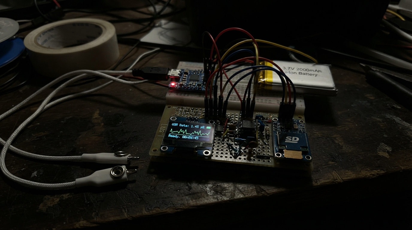
This professional GSR (galvanic skin response) module captures real-time psychophysiological data using a transimpedance amplifier and high-resolution ADC. Built around an ESP32 microcontroller, the system measures skin conductance through reusable Ag/AgCl electrodes, processes the signal with a precision op-amp circuit, and logs data to a microSD card for offline analysis. The module operates independently on a rechargeable lithium battery with USB charging support.
This guide provides a complete wiring diagram, parts list, and step-by-step assembly instructions for building a portable GSR sensor. You'll learn how to construct the isolated power supply, configure the transimpedance amplifier with proper biasing, shield the electrode leads from noise, and deploy the firmware for autonomous data collection without a computer connection.
Wiring diagram

Gather all the parts
Assemble it in 6 steps
1. Monte a alimentação isolada
Com a bateria desconectada, ligue BAT+ da bateria ao pino BAT da placa carregadora e ligue BAT− ao GND. Ligue a saída 3V3 da placa carregadora ao pino 3V3 do ESP32, do ADS1115 e do módulo microSD; ligue todos os GND ao mesmo GND. A porta USB da placa carregadora serve apenas para carregar a bateria, nunca para uma sessão de medição.
- Monte tudo em uma caixa plástica fechada depois de testar.
- Durante a coleta, mantenha qualquer cabo USB fora do ESP32 e do carregador.
- Não conecte USB, carregador de tomada ou computador enquanto os eletrodos estiverem presos a uma pessoa; isso elimina a separação por bateria deste protótipo.
2. Ligue o conversor de leitura
Ligue VDD do ADS1115 a 3V3 (alimentação), GND a GND (terra), SDA ao GPIO21 (dados) e SCL ao GPIO22 (dados). Ligue também ADDR ao GND; isso define o endereço que o programa procura.
- Use fios curtos e mantenha SDA e SCL longe dos cabos dos eletrodos.
3. Monte a referência de meio volt
Coloque o resistor de 56 kΩ entre 3V3 e um ponto vazio da protoboard. Coloque o resistor de 10 kΩ entre esse mesmo ponto e GND. Ligue esse ponto ao pino 1IN+ do MCP6002 e a uma perna do capacitor de 100 nF; a outra perna do capacitor vai ao GND. Ligue 1OUT diretamente a 1IN−. No MCP6002, ligue VDD a 3V3 e VSS a GND.
- O ponto comum dos dois resistores é a pequena tensão de teste, perto de 0,5 V.
- Confirme o encaixe do MCP6002: o ponto ou meia-lua do encapsulamento marca o lado do pino 1.
- Um MCP6002 girado ao contrário pode aquecer ou ser danificado quando a bateria for conectada.
4. Monte o caminho protegido dos eletrodos
Ligue 1OUT ao primeiro resistor de 100 kΩ. Ligue a outra ponta desse resistor ao fio ELECTRODE_A. Ligue o fio ELECTRODE_B ao pino 2IN−. Ligue 2IN+ ao GND. Coloque o segundo resistor de 100 kΩ entre 2OUT e 2IN−. Por fim, ligue 2OUT ao AIN0 do ADS1115.
- Deixe os dois resistores de 100 kΩ próximos ao MCP6002, não junto à pele.
- Trance levemente os dois fios dos eletrodos e mantenha-os afastados do ESP32 e do cartão.
- Não substitua nem faça ponte no resistor de 100 kΩ que vai ao ELECTRODE_A: ele é a barreira que limita a corrente de teste.
5. Ligue o cartão de dados
Ligue VCC do módulo microSD a 3V3 (alimentação), GND a GND (terra), MOSI ao GPIO23 (dados), MISO ao GPIO19 (dados), SCK ao GPIO18 (relógio) e CS ao GPIO4 (seleção do cartão). Coloque um cartão microSD formatado em FAT32 no módulo antes de ligar a bateria.
- Use um módulo microSD que aceite sinais e alimentação de 3,3 V.
- O programa cria GSR000.CSV, depois GSR001.CSV e assim por diante; retire a bateria antes de remover o cartão.
- Não retire o cartão enquanto a bateria estiver ligada, pois isso pode corromper o arquivo que está sendo gravado.
6. Faça a coleta sem USB
Limpe e seque suavemente dois pontos da mesma mão, prenda os dois eletrodos Ag/AgCl e então ligue somente a bateria. Deixe a pessoa quieta por alguns minutos antes de marcar o início da sessão no seu caderno. Desligue a bateria antes de tirar os eletrodos ou conectar um cabo USB.
- Faça uma medição com um resistor conhecido de 100 kΩ no lugar da pessoa antes de cada conjunto de sessões.
- O arquivo CSV é para análise de pesquisa; mantenha junto dele notas sobre participante, condição, horário e qualquer estímulo.
- Este é um registrador experimental de pesquisa, não um dispositivo médico, diagnóstico ou certificado. Não use em pessoas com marca-passo, implantes eletrônicos, lesão de pele, ou durante procedimentos clínicos.
Review all connections
1. Connections between "battery_1" and "ESP32"
2. Connections between "charger_3v3_1" and "ESP32"
3. Connections between "ads1115_1" and "ESP32"
4. Connections between "microsd_1" and "ESP32"
5. Connections between "opamp_mcp6002_1" and "ESP32"
6. Connections between "r_ref_top_56k" and "ESP32"
7. Connections between "r_ref_bottom_10k" and "ESP32"
8. Connections between "c_ref_100nf" and "ESP32"
9. Connections between "r_source_100k" and "ESP32"
10. Connections between "electrodes_agcl_1" and "ESP32"
11. Connections between "r_feedback_100k" and "ESP32"
Deploy the firmware
#include <Arduino.h>
#include <Wire.h>
#include <SPI.h>
#include <SD.h>
#include <Adafruit_ADS1X15.h>
#include <WiFi.h>

constexpr int I2C_SDA_PIN = 21;
constexpr int I2C_SCL_PIN = 22;
constexpr int SD_CS_PIN = 4;
constexpr int SD_MOSI_PIN = 23;
constexpr int SD_MISO_PIN = 19;
constexpr int SD_SCK_PIN = 18;
constexpr float TEST_REFERENCE_V = 0.500f;
constexpr float FEEDBACK_RESISTOR_OHM = 100000.0f;
constexpr uint32_t SAMPLE_INTERVAL_MS = 100;

Adafruit_ADS1115 ads;
File logFile;
uint32_t lastSampleMs = 0;

[[noreturn]] void stopWithError(const char *message) {
  Serial.println(message);
  while (true) {
    delay(1000);
  }
}

String nextLogName() {
  for (int i = 0; i < 1000; ++i) {
    char candidate[16];
    snprintf(candidate, sizeof(candidate), "/GSR%03d.CSV", i);
    if (!SD.exists(candidate)) {
      return String(candidate);
    }
  }
  return String("/GSR999.CSV");
}

float readTiaVolts(int16_t &rawOut) {
  int32_t total = 0;
  constexpr int COUNT = 4;
  for (int i = 0; i < COUNT; ++i) {
    total += ads.readADC_SingleEnded(0);
  }
  rawOut = static_cast<int16_t>(total / COUNT);
  // ADS1115 at GAIN_TWO: one count represents 0.0625 mV.
  return static_cast<float>(rawOut) * 0.0000625f;
}

void logSample() {
  int16_t raw = 0;
  const float tiaVolts = readTiaVolts(raw);
  // I = Vout / Rf.  The equal 100 kOhm series resistor means the skin
  // voltage is approximately 0.500 V - Vout.
  const float skinVolts = TEST_REFERENCE_V - tiaVolts;
  float conductanceUS = NAN;
  if (tiaVolts >= 0.0f && skinVolts > 0.010f) {
    const float currentA = tiaVolts / FEEDBACK_RESISTOR_OHM;
    conductanceUS = (currentA / skinVolts) * 1000000.0f;
  }

  const uint32_t now = millis();
  logFile.print(now);
  logFile.print(',');
  logFile.print(raw);
  logFile.print(',');
  logFile.print(tiaVolts, 6);
  logFile.print(',');
  if (isnan(conductanceUS)) {
    logFile.println("NaN");
  } else {
    logFile.println(conductanceUS, 4);
  }
  logFile.flush();

  Serial.print(now);
  Serial.print(" ms, ");
  Serial.print(tiaVolts, 6);
  Serial.print(" V, ");
  if (isnan(conductanceUS)) {
    Serial.println("out of range");
  } else {
    Serial.print(conductanceUS, 4);
    Serial.println(" uS");
  }
}

void setup() {
  Serial.begin(115200);
  WiFi.mode(WIFI_OFF);

  Wire.begin(I2C_SDA_PIN, I2C_SCL_PIN);
  if (!ads.begin(0x48, &Wire)) {
    stopWithError("ADS1115 not found; disconnect the battery before checking its SDA and SCL wires.");
  }
  ads.setGain(GAIN_TWO);
  ads.setDataRate(RATE_ADS1115_128SPS);

  SPI.begin(SD_SCK_PIN, SD_MISO_PIN, SD_MOSI_PIN, SD_CS_PIN);
  if (!SD.begin(SD_CS_PIN, SPI, 1000000)) {
    stopWithError("microSD card not found; disconnect the battery before checking the card and its wires.");
  }

  const String filename = nextLogName();
  logFile = SD.open(filename.c_str(), FILE_WRITE);
  if (!logFile) {
    stopWithError("Could not create the CSV file on the microSD card.");
  }
  logFile.println("time_ms,ads_counts,tia_volts,conductance_uS");
  logFile.flush();
  Serial.print("Logging to ");
  Serial.println(filename);
}

void loop() {
  const uint32_t now = millis();
  if (now - lastSampleMs >= SAMPLE_INTERVAL_MS) {
    lastSampleMs = now;
    logSample();
  }
}
Remix this project
Make it yours in one click
Open a full copy of this project in your own Schematik workspace — diagram, code, parts, and assembly steps included. Swap the sensor, add features, or redesign the whole thing with AI. The author's original stays untouched.