Community project
ESP32 Energy Monitor Control
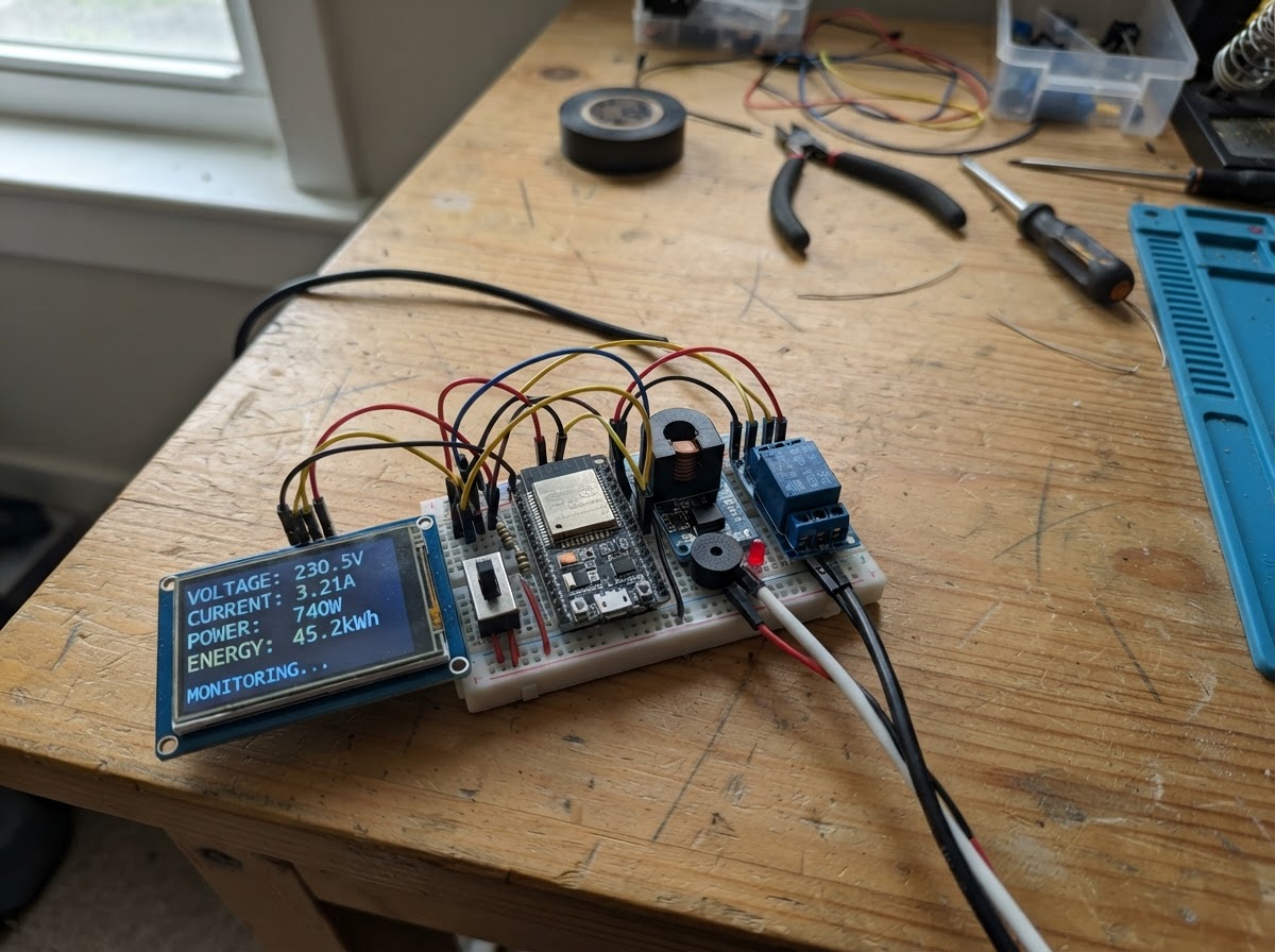
This project builds a real-time energy monitor and control system using an ESP32 microcontroller paired with a PZEM-004T power meter and ILI9341 touchscreen display. The system measures voltage, current, power consumption, and energy usage while providing relay-based load control and overcurrent protection via an audible alarm.
Builders will receive a complete wiring diagram, parts list, and step-by-step assembly instructions that prioritize testing the display first before integrating the power sensing and control modules. The firmware includes a web interface for remote monitoring and control, making this ideal for tracking energy consumption in workshops, labs, or home automation setups.
Wiring diagram

Gather all the parts
Assemble it in 4 steps
1. Mount the ESP32 across the two breadboards
Place the two breadboards side-by-side. Mount the ESP32 across their facing inner edges so there are accessible terminal holes beside both pin rows. Keep the USB connector reachable.
- Use only the central terminal strips for signal jumpers; the red/blue rails are for power and ground distribution.
- Do not connect mains wiring, PZEM AC terminals, or relay COM/NO/NC terminals to either breadboard.
2. Connect and test the TFT first
With USB disconnected, wire the TFT: VCC and LED to ESP32 3V3; GND to ESP32 GND; SDI/MOSI to GPIO23; SDO/MISO to GPIO19; SCK to GPIO18; CS to GPIO5; DC to GPIO2; and RESET to GPIO4. Leave touch and SD-card pins disconnected for the first test.
- The TFT uses 3.3 V, not 5 V.
- The web dashboard firmware also displays its address on the TFT after it starts.
- Recheck VCC, LED, and GND before USB power is connected.
3. Deploy and join the ESP32 Wi-Fi network
Power the ESP32 from USB and press Schematik's Deploy button. On a phone or computer, open Wi-Fi settings and join the network named PowerMonitor-ESP32 using password monitor123. Then open a browser and go to http://192.168.4.1.
- This is a local web app hosted directly by the ESP32. Your phone may report that the network has no internet; stay connected anyway.
- The dashboard is read-only and refreshes measurements every two seconds.
- Change the default Wi-Fi password in the firmware before using this project outside a private demonstration.
4. Add the remaining low-voltage modules after the display test
With USB unplugged, connect PZEM RX to GPIO17; connect PZEM TX through the 10 kΩ / 20 kΩ divider to GPIO16; connect relay IN1, IN2, IN3 to GPIO25, GPIO26, GPIO33; connect the SPDT COM to GPIO14 and one outer switch terminal to GND. Add the buzzer only with a suitable transistor driver.
- All low-voltage modules need a common GND with the ESP32.
- The physical SPDT switch is the relay enable control.
- A bare two-pin buzzer must not be driven directly from an ESP32 GPIO; use an NPN transistor driver.
- The PZEM TX divider requires both the listed 10 kΩ resistor and a physical 20 kΩ resistor from the divider junction to GND.
Review all connections
1. Connections between "tft_1" and "ESP32"
2. Connections between "pzem_1" and "ESP32"
3. Connections between "pzem_tx_resistor_top" and "ESP32"
4. Connections between "relay_3ch_1" and "ESP32"
5. Connections between "spdt_switch_1" and "ESP32"
6. Connections between "buzzer_1" and "ESP32"
Deploy the firmware
#include <Arduino.h>
#include <SPI.h>
#include <WiFi.h>
#include <WebServer.h>
#include <Adafruit_GFX.h>
#include <Adafruit_ILI9341.h>
#include <PZEM004Tv30.h>


// Forward declarations

// Forward declarations
void handleRelay();

void setRelays(bool on);
void statusLine(const char *s,uint16_t color);
void drawHeader();
void drawReadings();
void drawError();
const char* getStatus();
void handleStatus();

constexpr uint8_t TFT_CS=5, TFT_DC=2, TFT_RST=4, TFT_SCK=18, TFT_MISO=19, TFT_MOSI=23;
constexpr uint8_t PZEM_RX=16, PZEM_TX=17, RELAY_1=25, RELAY_2=26, RELAY_3=33, BUZZER_PIN=32, RELAY_ENABLE_SWITCH=14;
constexpr float OVERCURRENT_A=10.0f, TARIFF_PER_KWH=0.20f;
constexpr uint32_t SAMPLE_INTERVAL_MS=2000, ALARM_TOGGLE_MS=300;
const char *AP_SSID="PowerMonitor-ESP32";
const char *AP_PASSWORD="monitor123";

Adafruit_ILI9341 tft(TFT_CS,TFT_DC,TFT_RST);
PZEM004Tv30 pzem(Serial2,PZEM_RX,PZEM_TX);
WebServer server(80);
bool tripped=false,buzzerOn=false,pzemValid=false,outputsOn=false;
bool webRequestedOn=true;
float measuredVoltage=NAN, measuredCurrent=NAN, measuredPower=NAN, measuredEnergy=NAN, measuredPf=NAN;
uint32_t lastSampleMs=0,lastAlarmMs=0;

const char WEB_PAGE[] PROGMEM=R"html(
<!doctype html><html><head><meta name="viewport" content="width=device-width,initial-scale=1"><title>Power Monitor</title><style>body{margin:0;background:#09131d;color:#edf7ff;font-family:Arial}.wrap{max-width:700px;margin:auto;padding:20px}h1{color:#4de1e8;margin:0 0 6px}.sub,.label,small{color:#aac2d0}.grid{display:grid;grid-template-columns:repeat(2,1fr);gap:12px}.card,#state{background:#132635;border-radius:12px;padding:16px}.value{font-size:28px;font-weight:bold;margin-top:5px}#state{margin-top:14px;text-align:center;font-weight:bold}.ok{background:#136b45!important}.warn{background:#926114!important}.bad{background:#9c2630!important}small{display:block;margin-top:20px}</style></head><body><main class="wrap"><h1>Power Monitor</h1><div class="sub">ESP32 local dashboard</div><section class="grid"><div class="card"><div class="label">Voltage</div><div class="value" id="v">-- V</div></div><div class="card"><div class="label">Current</div><div class="value" id="i">-- A</div></div><div class="card"><div class="label">Power</div><div class="value" id="p">-- W</div></div><div class="card"><div class="label">Energy</div><div class="value" id="e">-- kWh</div></div><div class="card"><div class="label">Power factor</div><div class="value" id="f">--</div></div><div class="card"><div class="label">Estimated cost</div><div class="value" id="c">--</div></div></section><div id="state">Connecting...</div><section class="card" style="margin-top:14px"><div class="label">Voice control</div><button onclick="listenVoice()" style="margin-top:10px;padding:12px;background:#4de1e8;border:0;border-radius:8px;font-weight:bold">Speak command</button><div id="voice" class="sub" style="margin-top:8px">Say “turn outputs on” or “turn outputs off”.</div></section><small>Voice ON still requires the physical SPDT enable switch to be ON, valid PZEM readings, and no over-current trip. Voice cannot reset a trip.</small></main><script>function n(v,d,u){return Number.isFinite(v)?v.toFixed(d)+u:'--'+u}async function u(){try{let s=await (await fetch('/api/status',{cache:'no-store'})).json();v.textContent=n(s.v,1,' V');i.textContent=n(s.i,2,' A');p.textContent=n(s.p,0,' W');e.textContent=n(s.e,3,' kWh');f.textContent=n(s.f,2,'');c.textContent=Number.isFinite(s.c)?s.c.toFixed(2):'--';state.textContent=s.s;state.className=s.t?'bad':s.o?'ok':'warn'}catch(x){state.textContent='Dashboard connection lost';state.className='bad'}}async function relayCommand(state){try{let r=await fetch('/api/relay?state='+state,{cache:'no-store'});let j=await r.json();voice.textContent=j.message;u()}catch(e){voice.textContent='Command could not reach the ESP32'}}function listenVoice(){let R=window.SpeechRecognition||window.webkitSpeechRecognition;if(!R){voice.textContent='Voice recognition is unavailable here. Use Chrome or Edge.';return}let r=new R();r.lang='en-US';r.interimResults=false;r.maxAlternatives=1;voice.textContent='Listening…';r.onresult=e=>{let text=e.results[0][0].transcript.toLowerCase();voice.textContent='Heard: '+text;if(text.includes('off')||text.includes('stop'))relayCommand('off');else if(text.includes('on')||text.includes('start'))relayCommand('on');else voice.textContent='Say: turn outputs on, or turn outputs off.'};r.onerror=e=>voice.textContent='Voice error: '+e.error;r.start()}u();setInterval(u,2000)</script></body></html>
)html";

void setRelays(bool on){digitalWrite(RELAY_1,on?LOW:HIGH);digitalWrite(RELAY_2,on?LOW:HIGH);digitalWrite(RELAY_3,on?LOW:HIGH);}
void statusLine(const char *s,uint16_t color){tft.fillRect(0,280,240,40,color);tft.setTextColor(ILI9341_WHITE,color);tft.setTextSize(2);tft.setCursor(10,292);tft.print(s);}
void drawHeader(){tft.fillScreen(ILI9341_BLACK);tft.fillRect(0,0,240,30,ILI9341_DARKCYAN);tft.setTextColor(ILI9341_WHITE,ILI9341_DARKCYAN);tft.setTextSize(2);tft.setCursor(8,8);tft.print("POWER MONITOR");tft.setTextColor(ILI9341_LIGHTGREY,ILI9341_BLACK);tft.setTextSize(1);tft.setCursor(8,39);tft.print("Web: 192.168.4.1");}
void drawReadings(){tft.fillRect(0,55,240,220,ILI9341_BLACK);tft.setTextSize(2);tft.setTextColor(ILI9341_CYAN,ILI9341_BLACK);tft.setCursor(10,62);tft.print("Voltage:");tft.setTextColor(ILI9341_WHITE,ILI9341_BLACK);tft.setCursor(130,62);tft.printf("%.1f V",measuredVoltage);tft.setTextColor(ILI9341_CYAN,ILI9341_BLACK);tft.setCursor(10,97);tft.print("Current:");tft.setTextColor(ILI9341_WHITE,ILI9341_BLACK);tft.setCursor(130,97);tft.printf("%.2f A",measuredCurrent);tft.setTextColor(ILI9341_CYAN,ILI9341_BLACK);tft.setCursor(10,132);tft.print("Power:");tft.setTextColor(ILI9341_WHITE,ILI9341_BLACK);tft.setCursor(130,132);tft.printf("%.0f W",measuredPower);tft.setTextColor(ILI9341_CYAN,ILI9341_BLACK);tft.setCursor(10,167);tft.print("Energy:");tft.setTextColor(ILI9341_WHITE,ILI9341_BLACK);tft.setCursor(130,167);tft.printf("%.3f kWh",measuredEnergy);tft.setTextColor(ILI9341_CYAN,ILI9341_BLACK);tft.setCursor(10,202);tft.print("PF:");tft.setTextColor(ILI9341_WHITE,ILI9341_BLACK);tft.setCursor(130,202);tft.printf("%.2f",measuredPf);}
void drawError(){tft.fillRect(0,55,240,220,ILI9341_BLACK);tft.setTextColor(ILI9341_RED,ILI9341_BLACK);tft.setTextSize(2);tft.setCursor(15,105);tft.print("PZEM READ ERROR");}
const char* getStatus(){if(!pzemValid)return "PZEM read error - outputs off";if(tripped)return "Tripped - overcurrent";if(!webRequestedOn)return "Web command off - outputs off";if(!outputsOn)return "Physical switch off - outputs off";return "Normal - outputs on";}
void handleStatus(){String j="{\"v\":"+String(measuredVoltage,2)+",\"i\":"+String(measuredCurrent,3)+",\"p\":"+String(measuredPower,1)+",\"e\":"+String(measuredEnergy,3)+",\"f\":"+String(measuredPf,2)+",\"c\":"+String(measuredEnergy*TARIFF_PER_KWH,2)+",\"o\":"+(outputsOn?"true":"false")+",\"t\":"+(tripped?"true":"false")+",\"s\":\""+getStatus()+"\"}";server.send(200,"application/json",j);}
void handleRelay(){String state=server.arg("state");if(state=="off"){webRequestedOn=false;setRelays(false);outputsOn=false;server.send(200,"application/json","{\"message\":\"Outputs requested OFF\"}");return;}if(state=="on"){webRequestedOn=true;if(tripped){server.send(423,"application/json","{\"message\":\"Trip is active; power-cycle ESP32 to reset\"}");return;}if(!pzemValid){server.send(423,"application/json","{\"message\":\"PZEM reading invalid; outputs remain off\"}");return;}if(digitalRead(RELAY_ENABLE_SWITCH)!=LOW){server.send(423,"application/json","{\"message\":\"Turn physical enable switch ON first\"}");return;}server.send(200,"application/json","{\"message\":\"Outputs requested ON\"}");return;}server.send(400,"application/json","{\"message\":\"Say on or off\"}");}
void setup(){
  // Configure outputs first. Relay modules are active-low, so drive HIGH immediately
  // afterwards to hold all relays de-energized at startup.
  pinMode(RELAY_1, OUTPUT);
  pinMode(RELAY_2, OUTPUT);
  pinMode(RELAY_3, OUTPUT);
  pinMode(BUZZER_PIN, OUTPUT);
  pinMode(RELAY_ENABLE_SWITCH, INPUT_PULLUP);
  setRelays(false);
  digitalWrite(BUZZER_PIN, LOW);
  Serial.begin(115200);Serial2.begin(9600,SERIAL_8N1,PZEM_RX,PZEM_TX);SPI.begin(TFT_SCK,TFT_MISO,TFT_MOSI,TFT_CS);tft.begin();tft.setRotation(1);drawHeader();statusLine("STARTING - OUTPUTS OFF",ILI9341_ORANGE);WiFi.mode(WIFI_AP);WiFi.softAP(AP_SSID,AP_PASSWORD);server.on("/",HTTP_GET,[](){server.send_P(200,"text/html",WEB_PAGE);});server.on("/api/status",HTTP_GET,handleStatus);server.on("/api/relay",HTTP_GET,handleRelay);server.begin();}
void loop(){server.handleClient();uint32_t now=millis();if(tripped&&now-lastAlarmMs>=ALARM_TOGGLE_MS){lastAlarmMs=now;buzzerOn=!buzzerOn;digitalWrite(BUZZER_PIN,buzzerOn?HIGH:LOW);}if(now-lastSampleMs<SAMPLE_INTERVAL_MS)return;lastSampleMs=now;measuredVoltage=pzem.voltage();measuredCurrent=pzem.current();measuredPower=pzem.power();measuredEnergy=pzem.energy();measuredPf=pzem.pf();pzemValid=!(isnan(measuredVoltage)||isnan(measuredCurrent)||isnan(measuredPower)||isnan(measuredEnergy)||isnan(measuredPf));if(!pzemValid){outputsOn=false;setRelays(false);digitalWrite(BUZZER_PIN,LOW);drawError();statusLine("FAULT - OUTPUTS OFF",ILI9341_RED);return;}drawReadings();bool enabled=digitalRead(RELAY_ENABLE_SWITCH)==LOW;if(!tripped&&measuredCurrent>=OVERCURRENT_A){tripped=true;outputsOn=false;setRelays(false);statusLine("TRIPPED - OVERCURRENT",ILI9341_RED);}else if(tripped){outputsOn=false;setRelays(false);statusLine("TRIPPED - POWER CYCLE TO RESET",ILI9341_RED);}else if(!enabled){outputsOn=false;setRelays(false);statusLine("SWITCH OFF - OUTPUTS OFF",ILI9341_ORANGE);}else if(!webRequestedOn){outputsOn=false;setRelays(false);statusLine("WEB OFF - OUTPUTS OFF",ILI9341_ORANGE);}else{outputsOn=true;setRelays(true);statusLine("NORMAL - OUTPUTS ON",ILI9341_DARKGREEN);}}
Remix this project
Make it yours in one click
Open a full copy of this project in your own Schematik workspace — diagram, code, parts, and assembly steps included. Swap the sensor, add features, or redesign the whole thing with AI. The author's original stays untouched.
Related projects

Create A Complete Electrical Schematic Esp32 Sma
ESP32 · September 17, 2026Ayansh Agrawal
ESP32 Kare Ekran Projeleri
ESP32 · September 16, 2026Seref Ai
Component Qty --------------------------- ------
ESP32 · September 16, 2026Yathartha Chakrawal