Community project
ESP32 Environmental Security Monitor
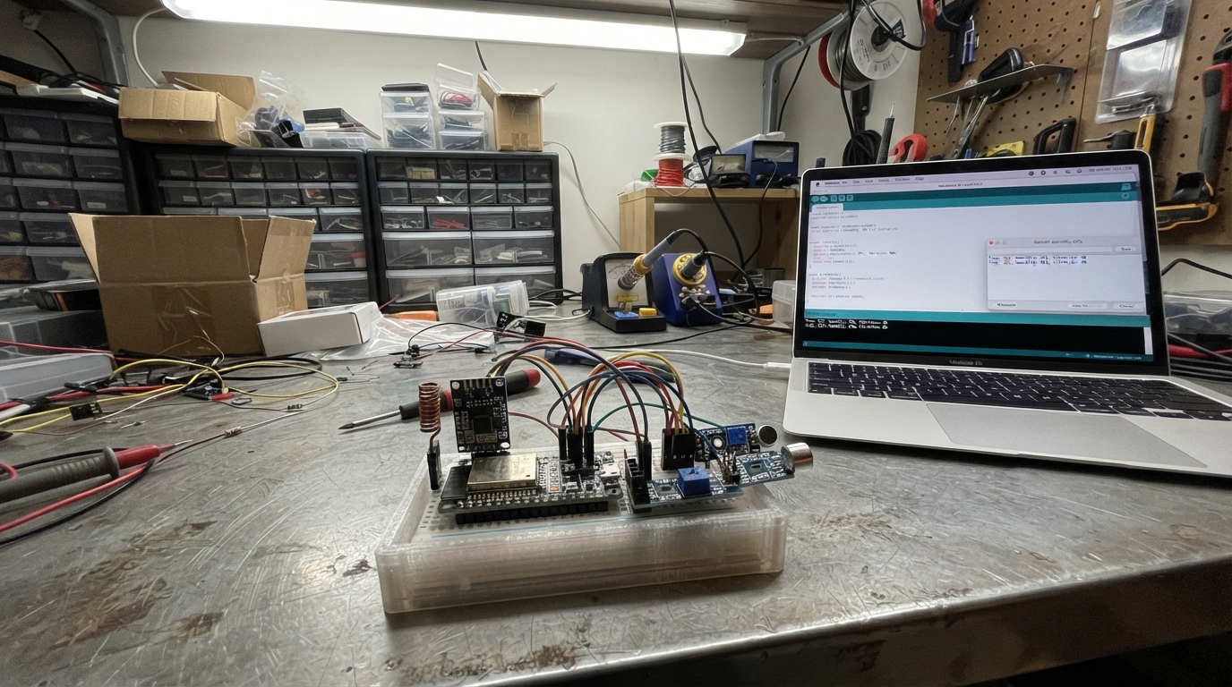
This ESP32-based security monitor combines multiple sensor types to detect environmental threats: sub-GHz RF reception for remote signals, digital audio analysis via I²S microphone, vibration detection, and acoustic trigger sensing. The guide provides a complete wiring diagram, parts list, and step-by-step assembly instructions to build a multi-modal event detector that logs and reports security events with cooldown throttling to prevent alert spam.
The firmware uses interrupt-driven RF reception, I²S audio sampling, and digital pin monitoring to capture events across all sensor modalities. Builders will receive the complete Arduino sketch, pinout reference, power distribution layout, and inspection checklist needed to assemble and deploy a working environmental security system.
Wiring diagram

Gather all the parts
Assemble it in 6 steps
1. Make the shared power rows
Place the ESP32-S3 board across the breadboard center gap. Run one red jumper from its 3V3 pin to the red power row and one black jumper from GND to the blue ground row. Use those same rows for every module below so all parts share the same electrical reference.
- Use only the ESP32 board’s 3V3 pin for these modules; none of them should be connected to 5V.
- Check that every module has one wire to the same ground row.
- Connecting the 3.3 V CC1101 or INMP441 to 5 V can permanently damage it.
2. Wire the RF receiver
Connect the CC1101 VCC pin to the 3V3 row and GND pin to the ground row. Connect MOSI to GPIO11, MISO to GPIO13, SCK to GPIO12, CSN to GPIO10, and GDO0 to GPIO14. Keep these jumper wires short and keep the receiver away from the ESP32 antenna end.
- VCC → 3V3 (power), GND → GND (ground), MOSI → GPIO11 (radio data), MISO → GPIO13 (radio data), SCK → GPIO12 (clock), CSN → GPIO10 (radio select), GDO0 → GPIO14 (received-message signal).
- This configuration listens at 433.92 MHz for messages from transmitters you own or are authorized to test.
- Never connect CC1101 VCC to 5V; it is a 3.3 V part.
- Do not use this project to capture or replay transmissions from devices you do not own or have permission to test.
3. Wire the digital microphone
Connect the INMP441 VDD pin to the 3V3 row, GND to the ground row, SCK to GPIO15, WS to GPIO16, SD to GPIO17, and L/R to the ground row. Place its small microphone opening where it can hear the room but is not touching a vibrating surface.
- VDD → 3V3 (power), GND → GND (ground), SCK → GPIO15 (microphone clock), WS → GPIO16 (timing signal), SD → GPIO17 (sound data), L/R → GND (left-channel selection).
- The firmware reports only a changing sound-level number; it does not save audio.
- Swapping VDD and GND can damage the microphone module.
4. Wire the vibration sensor
Connect the SW-420 VCC pin to the 3V3 row, GND to the ground row, and DO to GPIO18. Turn the small adjustment screw fully counter-clockwise first, then increase it slowly during testing until a firm tap creates an event.
- VCC → 3V3 (power), GND → GND (ground), DO → GPIO18 (knock and movement signal).
- Tape or mount this module to the item or enclosure whose movement you want to notice.
- Do not power the module from 5 V because its signal would then be too high for the ESP32 input.
5. Wire the loud-noise trigger
Connect the KY-038 VCC pin to the 3V3 row, GND to the ground row, and DO to GPIO21. Leave AO unconnected. Adjust its small screw while watching the sensor’s indicator light: set it so ordinary room noise does not trigger it but a deliberate clap does.
- VCC → 3V3 (power), GND → GND (ground), DO → GPIO21 (adjustable loud-noise signal).
- The separate INMP441 provides a more useful measured sound-level reading; this module gives a simple adjustable trigger.
- Leave the KY-038 AO pin disconnected in this build; it is not used by the firmware.
6. Inspect before powering
Trace each module’s VCC wire back to 3V3 and each GND wire back to the common ground row. Ensure no loose wire bridges neighboring ESP32 pins, then plug the ESP32-S3 into USB.
- A correct startup message says that vibration, sound trigger, microphone level, and approved RF messages are ready.
- If the RF receiver is not detected, first recheck its six signal wires and its 3V3 wire.
- Unplug USB before moving jumper wires; a slipped live wire can short the 3.3 V supply.
Review all connections
1. Connections between "rf_receiver" and "ESP32"
2. Connections between "inmp441_mic" and "ESP32"
3. Connections between "vibration_sensor" and "ESP32"
4. Connections between "sound_sensor" and "ESP32"
Deploy the firmware
#include <Arduino.h>
#include <SPI.h>
#include <RadioLib.h>
#include <driver/i2s.h>


// Forward declarations
void IRAM_ATTR onRfPacket();
bool eventAllowed();
void reportEvent(const char *eventName, int32_t value);
void setupI2sMicrophone();
int32_t readMicrophoneLevel();
void setupRadio();
void checkRadio();
void checkDigitalSensors();
void checkMicrophone();

constexpr int CC1101_CS_PIN = 10;
constexpr int CC1101_MOSI_PIN = 11;
constexpr int CC1101_SCK_PIN = 12;
constexpr int CC1101_MISO_PIN = 13;
constexpr int CC1101_GDO0_PIN = 14;
constexpr int MIC_SCK_PIN = 15;
constexpr int MIC_WS_PIN = 16;
constexpr int MIC_SD_PIN = 17;
constexpr int VIBRATION_PIN = 18;
constexpr int SOUND_TRIGGER_PIN = 21;

constexpr uint32_t EVENT_COOLDOWN_MS = 1500;
constexpr uint32_t SOUND_SAMPLE_INTERVAL_MS = 250;
constexpr int32_t MIC_EVENT_LEVEL = 180000;

SPIClass radioSpi(FSPI);
CC1101 radio = new Module(CC1101_CS_PIN, CC1101_GDO0_PIN, RADIOLIB_NC, RADIOLIB_NC, radioSpi);
volatile bool rfPacketReady = false;
bool radioReady = false;
uint32_t lastEventAt = 0;
uint32_t lastMicSampleAt = 0;
int lastVibrationState = HIGH;
int lastSoundState = HIGH;

void IRAM_ATTR onRfPacket() {
  rfPacketReady = true;
}

bool eventAllowed() {
  const uint32_t now = millis();
  if (now - lastEventAt < EVENT_COOLDOWN_MS) {
    return false;
  }
  lastEventAt = now;
  return true;
}

void reportEvent(const char *eventName, int32_t value = 0) {
  if (eventAllowed()) {
    Serial.printf("EVENT,%lu,%s,%ld\n", millis(), eventName, static_cast<long>(value));
  }
}

void setupI2sMicrophone() {
  const i2s_config_t config = {
    .mode = static_cast<i2s_mode_t>(I2S_MODE_MASTER | I2S_MODE_RX),
    .sample_rate = 16000,
    .bits_per_sample = I2S_BITS_PER_SAMPLE_32BIT,
    .channel_format = I2S_CHANNEL_FMT_ONLY_LEFT,
    .communication_format = I2S_COMM_FORMAT_STAND_I2S,
    .intr_alloc_flags = 0,
    .dma_buf_count = 4,
    .dma_buf_len = 64,
    .use_apll = false,
    .tx_desc_auto_clear = false,
    .fixed_mclk = 0
  };
  const i2s_pin_config_t pins = {
    .bck_io_num = MIC_SCK_PIN,
    .ws_io_num = MIC_WS_PIN,
    .data_out_num = I2S_PIN_NO_CHANGE,
    .data_in_num = MIC_SD_PIN
  };
  i2s_driver_install(I2S_NUM_0, &config, 0, nullptr);
  i2s_set_pin(I2S_NUM_0, &pins);
}

int32_t readMicrophoneLevel() {
  int32_t samples[64];
  size_t bytesRead = 0;
  const esp_err_t result = i2s_read(I2S_NUM_0, samples, sizeof(samples), &bytesRead, 20 / portTICK_PERIOD_MS);
  if (result != ESP_OK || bytesRead < sizeof(int32_t)) {
    return 0;
  }

  const size_t count = bytesRead / sizeof(int32_t);
  int64_t total = 0;
  for (size_t i = 0; i < count; ++i) {
    const int32_t sample = samples[i] >> 8;
    total += sample < 0 ? -static_cast<int64_t>(sample) : sample;
  }
  return static_cast<int32_t>(total / count);
}

void setupRadio() {
  radioSpi.begin(CC1101_SCK_PIN, CC1101_MISO_PIN, CC1101_MOSI_PIN, CC1101_CS_PIN);
  const int state = radio.begin(433.92);
  if (state == RADIOLIB_ERR_NONE) {
    radio.setGdo0Action(onRfPacket);
    radio.startReceive();
    radioReady = true;
    Serial.println("RF receiver ready at 433.92 MHz");
  } else {
    Serial.printf("RF receiver not detected, RadioLib error %d\n", state);
  }
}

void checkRadio() {
  if (!radioReady || !rfPacketReady) {
    return;
  }
  rfPacketReady = false;
  String message;
  const int state = radio.readData(message);
  if (state == RADIOLIB_ERR_NONE) {
    Serial.printf("RF_MESSAGE,%lu,%s\n", millis(), message.c_str());
    reportEvent("RF_MESSAGE");
  } else {
    Serial.printf("RF packet ignored, RadioLib error %d\n", state);
  }
  radio.startReceive();
}

void checkDigitalSensors() {
  const int vibrationState = digitalRead(VIBRATION_PIN);
  if (vibrationState != lastVibrationState) {
    lastVibrationState = vibrationState;
    reportEvent("VIBRATION", vibrationState);
  }

  const int soundState = digitalRead(SOUND_TRIGGER_PIN);
  if (soundState == LOW && lastSoundState == HIGH) {
    reportEvent("LOUD_SOUND_TRIGGER");
  }
  lastSoundState = soundState;
}

void checkMicrophone() {
  if (millis() - lastMicSampleAt < SOUND_SAMPLE_INTERVAL_MS) {
    return;
  }
  lastMicSampleAt = millis();
  const int32_t level = readMicrophoneLevel();
  Serial.printf("MIC_LEVEL,%lu,%ld\n", millis(), static_cast<long>(level));
  if (level >= MIC_EVENT_LEVEL) {
    reportEvent("MIC_LOUD_SOUND", level);
  }
}

void setup() {
  Serial.begin(115200);
  delay(300);
  Serial.println("Eagle Sentinel: sensor-only V1 starting");

  pinMode(VIBRATION_PIN, INPUT_PULLUP);
  pinMode(SOUND_TRIGGER_PIN, INPUT_PULLUP);
  lastVibrationState = digitalRead(VIBRATION_PIN);
  lastSoundState = digitalRead(SOUND_TRIGGER_PIN);

  setupI2sMicrophone();
  setupRadio();
  Serial.println("Ready: vibration, sound trigger, microphone level, and approved RF messages.");
}

void loop() {
  checkDigitalSensors();
  checkMicrophone();
  checkRadio();
  delay(5);
}
Remix this project
Make it yours in one click
Open a full copy of this project in your own Schematik workspace — diagram, code, parts, and assembly steps included. Swap the sensor, add features, or redesign the whole thing with AI. The author's original stays untouched.