Community project
ESP32 GPS Tracker
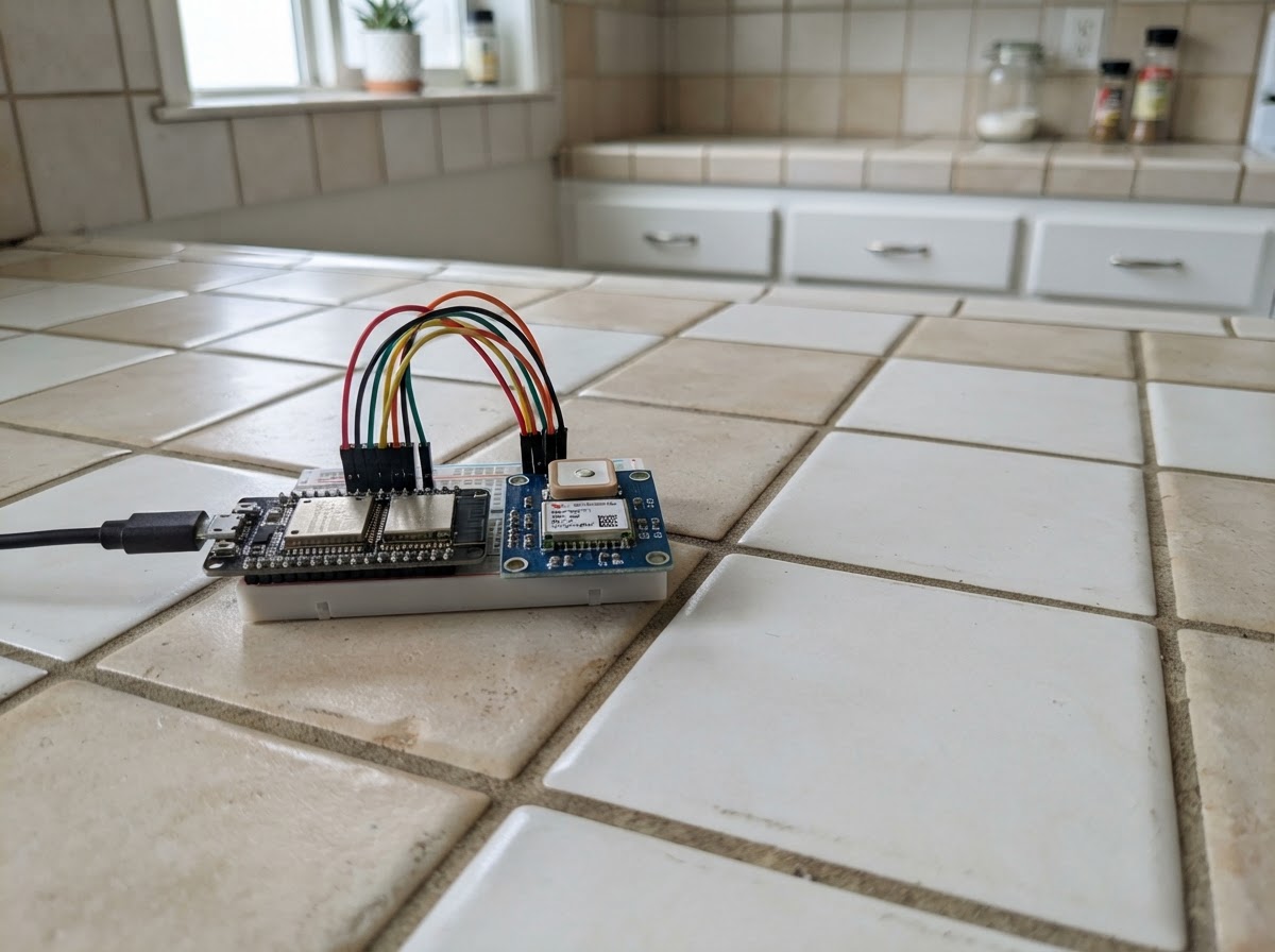
This project turns an ESP32 microcontroller into a GPS tracker that reads location data from a NEO-6M GPS module. The tracker reports latitude, longitude, altitude, speed, satellite count, and signal quality through the serial monitor, making it useful for logging position data, building location-aware applications, or understanding how GPS receivers work.
The guide includes a complete wiring diagram showing how to connect the GPS module to the ESP32's UART pins, a full parts list, and ready-to-upload firmware based on the TinyGPS++ library. Assembly takes just a few minutes: power down before wiring, connect the GPS module's power and serial lines to the ESP32, position the antenna outdoors or near a window, and upload the code to start receiving fixes.
Wiring diagram

Gather all the parts
Assemble it in 4 steps
1. Power off before wiring
Disconnect the ESP32 DevKit v1 from USB while you make the connections.
- Use short jumper wires and keep the GPS antenna facing upward.
- Do not connect the GPS module VCC to the ESP32 5V pin unless your exact breakout explicitly states it accepts 5V. This design uses 3.3V.
2. Connect GPS power
Connect gps_1 VCC to the ESP32 3V3 pin. Connect gps_1 GND to an ESP32 GND pin.
- GPS and ESP32 must share ground for UART data to work.
- Check the VCC and GND labels carefully; reversing power can damage the GPS module.
3. Connect the GPS UART
Connect gps_1 TX to ESP32 GPIO16. Connect gps_1 RX to ESP32 GPIO17. TX and RX are crossed because each device transmits to the other device's receiver.
- The tracker only requires TX-to-GPIO16 to receive location data; RX-to-GPIO17 is included for future GPS configuration.
- Leave the PPS pin unconnected.
- Use only 3.3V UART logic. Do not connect a 5V serial signal to ESP32 GPIO16 or GPIO17.
4. Position the antenna
Place the GPS module where its patch antenna has a clear view of the sky, ideally outdoors. Then reconnect USB power to the ESP32.
- The first satellite fix can take several minutes, especially after the module has been unused or moved a long distance.
- After Deploy, view the USB serial output at 115200 baud to see the readings.
- Indoor operation or metal enclosures can prevent a satellite fix.
Review all connections
1. Connections between "gps_1" and "ESP32"
Deploy the firmware
#include <Arduino.h>
#include <TinyGPS++.h>


// Forward declarations
void printLocation();

constexpr int GPS_RX_PIN = 16;  // ESP32 RX2 <- GPS TX
constexpr int GPS_TX_PIN = 17;  // ESP32 TX2 -> GPS RX
constexpr uint32_t GPS_BAUD = 9600;
constexpr uint32_t REPORT_INTERVAL_MS = 1000;

TinyGPSPlus gps;
HardwareSerial gpsSerial(2);
unsigned long lastReportMs = 0;

void printLocation() {
  if (gps.location.isValid()) {
    Serial.print("Latitude: ");
    Serial.println(gps.location.lat(), 6);
    Serial.print("Longitude: ");
    Serial.println(gps.location.lng(), 6);
  } else {
    Serial.println("Location: waiting for a GPS fix");
  }

  if (gps.altitude.isValid()) {
    Serial.print("Altitude: ");
    Serial.print(gps.altitude.meters(), 1);
    Serial.println(" m");
  }

  if (gps.speed.isValid()) {
    Serial.print("Speed: ");
    Serial.print(gps.speed.kmph(), 1);
    Serial.println(" km/h");
  }

  if (gps.satellites.isValid()) {
    Serial.print("Satellites: ");
    Serial.println(gps.satellites.value());
  }

  if (gps.hdop.isValid()) {
    Serial.print("HDOP: ");
    Serial.println(gps.hdop.hdop(), 1);
  }

  Serial.println("---");
}

void setup() {
  Serial.begin(115200);
  gpsSerial.begin(GPS_BAUD, SERIAL_8N1, GPS_RX_PIN, GPS_TX_PIN);

  Serial.println();
  Serial.println("ESP32 GPS tracker starting");
  Serial.println("Place the GPS antenna outdoors or beside a clear window.");
}

void loop() {
  while (gpsSerial.available() > 0) {
    gps.encode(gpsSerial.read());
  }

  const unsigned long now = millis();
  if (now - lastReportMs >= REPORT_INTERVAL_MS) {
    lastReportMs = now;
    printLocation();

    if (millis() > 5000 && gps.charsProcessed() < 10) {
      Serial.println("No GPS serial data received. Check TX-to-GPIO16, power, and ground.");
    }
  }
}
Remix this project
Make it yours in one click
Open a full copy of this project in your own Schematik workspace — diagram, code, parts, and assembly steps included. Swap the sensor, add features, or redesign the whole thing with AI. The author's original stays untouched.