Community project
ESP32 Home Appliance Remote Control
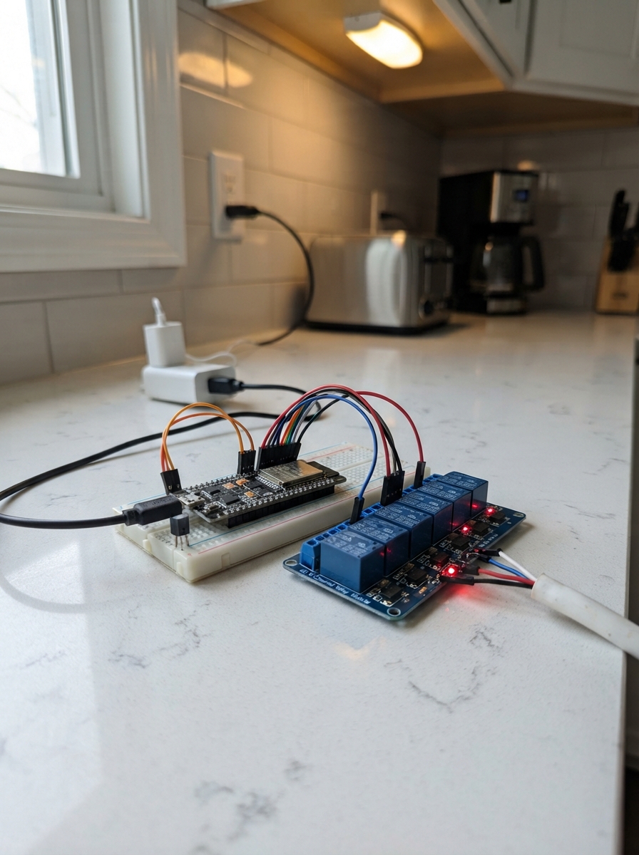
This project turns an ESP32 microcontroller into an infrared-controlled relay hub for home appliances. Using a VS1838B infrared receiver and an 8-channel opto-isolated relay module, the system decodes standard NEC remote commands and switches mains-powered devices like lights and fans safely through low-voltage control signals.
The guide provides a complete wiring diagram showing how to connect the infrared receiver to the ESP32, route relay control pins to the opto-isolated module, and safely integrate mains loads. Builders will receive a full parts list, step-by-step assembly instructions emphasizing safe mains handling, Arduino firmware with NEC protocol decoding, and testing procedures to verify each remote command triggers the correct relay output.
Wiring diagram

Gather all the parts
Assemble it in 6 steps
1. Keep the mains side enclosed
Turn off the building power at the breaker. Mount the ESP32, relay board, and 5 V supply in a non-conductive enclosure with a separate covered area for all mains wires. Have a qualified electrician identify the fan’s neutral, earth, and low/medium/high speed-tap wires before anything is connected.
- Label the three fan speed wires before disconnecting the old selector, because the labels prevent a low and high wire being mixed up later.
- Mains wiring can cause fatal shock or fire. Do not work on it live, and do not leave mains terminals exposed.
2. Power the low-voltage parts
Connect the wall supply’s 5 V output to the ESP32 VIN or 5V pin and to relay_board_1 VCC (power). Connect the supply ground to the ESP32 GND pin and relay_board_1 GND (ground). The ESP32 and relay board need this shared ground so the control signals have a reference.
- Use a 5 V supply rated for at least 2 A so the relay coils do not make the ESP32 reset when several relays switch.
- Make sure 5 V and GND are not swapped — swapped power can damage the ESP32 or relay board. Keep this low-voltage wiring physically separate from mains wiring.
3. Connect the infrared receiver
On ir_receiver_1, connect VCC to ESP32 3V3 (power), GND to ESP32 GND (ground), and OUT to GPIO27 (signal). Aim the receiver’s dark front window toward the room where the handset will be used.
- Check the lettering on your receiver module before plugging it in: VS1838B modules vary in physical pin order even though their labels are the same.
- Do not connect the receiver VCC to 5 V — use the ESP32 3V3 pin so its OUT signal stays safe for the ESP32.
4. Connect the relay control pins
Connect relay_board_1 IN1 to ESP32 GPIO16 (light 1 signal), IN2 to GPIO17 (light 2 signal), IN3 to GPIO18 (fan low-speed signal), IN4 to GPIO19 (fan medium-speed signal), and IN5 to GPIO23 (fan high-speed signal). Leave IN6 through IN8 unused.
- The relay board usually clicks when a channel turns on. This is normal and helps you identify the channel during a low-voltage test.
- Do not connect any relay screw terminal to an ESP32 GPIO pin — the screw terminals are for the isolated load contacts, not low-voltage signals.
5. Have the loads connected safely
A qualified electrician should connect fused mains live to COM1 and COM2, then connect NO1 to light 1 live and NO2 to light 2 live. For the fan, connect the same fused live feed to COM3, COM4, and COM5, then connect NO3 only to the fan low-speed tap, NO4 only to the medium-speed tap, and NO5 only to the high-speed tap. Keep the fan neutral and protective earth connected as required by the fan and local electrical code.
- COM means the incoming switched supply; NO means the outgoing wire is disconnected when that relay is off.
- Never connect two fan speed taps together. The firmware releases all three fan relays before selecting one, but the physical wires must also go to their matching terminals. Use relay contacts rated above the fan and light load, and use an electrician if you are not licensed for fixed wiring.
6. Test each remote command
With the enclosure closed and mains wiring inspected, power the 5 V supply. Point the matching 21-key NEC infrared handset at the receiver: press 1 for light 1, 2 for light 2, 4 for fan low, 5 for fan medium, 6 for fan high, and STOP for fan off.
- Test the fan starting at low speed, then turn it off before checking the other speeds. The commands ignore a held button so one quick press makes one change.
- If the fan does not match the selected speed, turn off the breaker and have the speed-tap labels checked; do not swap wires while powered.
Review all connections
1. Connections between "wall_supply_1" and "ESP32"
2. Connections between "ir_receiver_1" and "ESP32"
3. Connections between "relay_board_1" and "ESP32"
Deploy the firmware
#include <Arduino.h>
#include <IRremote.hpp>

enum class FanSpeed { OFF, LOW, MEDIUM, HIGH };


// Forward declarations
void writeRelay(uint8_t pin, bool on);
void setFanSpeed(FanSpeed nextSpeed);
void printStatus();

constexpr uint8_t IR_RECEIVE_PIN = 27;
constexpr uint8_t RELAY_LIGHT_1 = 16;
constexpr uint8_t RELAY_LIGHT_2 = 17;
constexpr uint8_t RELAY_FAN_LOW = 18;
constexpr uint8_t RELAY_FAN_MEDIUM = 19;
constexpr uint8_t RELAY_FAN_HIGH = 23;

// Common 21-key NEC handset commands. The serial log prints unknown command
// values, making a different compatible remote straightforward to map.
constexpr uint8_t KEY_1 = 0x0C;
constexpr uint8_t KEY_2 = 0x18;
constexpr uint8_t KEY_4 = 0x08;
constexpr uint8_t KEY_5 = 0x1C;
constexpr uint8_t KEY_6 = 0x5A;
constexpr uint8_t KEY_STOP = 0x4A;

bool light1On = false;
bool light2On = false;
FanSpeed fanSpeed = FanSpeed::OFF;

void writeRelay(uint8_t pin, bool on) {
  // Typical opto-isolated relay boards switch when their input is LOW.
  digitalWrite(pin, on ? LOW : HIGH);
}

void setFanSpeed(FanSpeed nextSpeed) {
  // Turn all speed contacts off before selecting one so speed taps are not joined.
  writeRelay(RELAY_FAN_LOW, false);
  writeRelay(RELAY_FAN_MEDIUM, false);
  writeRelay(RELAY_FAN_HIGH, false);
  delay(80);

  if (nextSpeed == FanSpeed::LOW) {
    writeRelay(RELAY_FAN_LOW, true);
  } else if (nextSpeed == FanSpeed::MEDIUM) {
    writeRelay(RELAY_FAN_MEDIUM, true);
  } else if (nextSpeed == FanSpeed::HIGH) {
    writeRelay(RELAY_FAN_HIGH, true);
  }
  fanSpeed = nextSpeed;
}

void printStatus() {
  Serial.print("Light 1: ");
  Serial.print(light1On ? "ON" : "OFF");
  Serial.print(", Light 2: ");
  Serial.print(light2On ? "ON" : "OFF");
  Serial.print(", Fan: ");
  if (fanSpeed == FanSpeed::OFF) Serial.println("OFF");
  else if (fanSpeed == FanSpeed::LOW) Serial.println("LOW");
  else if (fanSpeed == FanSpeed::MEDIUM) Serial.println("MEDIUM");
  else Serial.println("HIGH");
}

void setup() {
  Serial.begin(115200);

  pinMode(RELAY_LIGHT_1, OUTPUT);
  pinMode(RELAY_LIGHT_2, OUTPUT);
  pinMode(RELAY_FAN_LOW, OUTPUT);
  pinMode(RELAY_FAN_MEDIUM, OUTPUT);
  pinMode(RELAY_FAN_HIGH, OUTPUT);

  writeRelay(RELAY_LIGHT_1, false);
  writeRelay(RELAY_LIGHT_2, false);
  setFanSpeed(FanSpeed::OFF);

  IrReceiver.begin(IR_RECEIVE_PIN, DISABLE_LED_FEEDBACK);
  Serial.println("IR home controller ready.");
  Serial.println("1: light 1 | 2: light 2 | 4: fan low | 5: fan medium | 6: fan high | STOP: fan off");
}

void loop() {
  if (!IrReceiver.decode()) return;

  if (!(IrReceiver.decodedIRData.flags & IRDATA_FLAGS_IS_REPEAT)) {
    const uint8_t command = IrReceiver.decodedIRData.command;
    Serial.print("Received command: 0x");
    Serial.println(command, HEX);

    if (command == KEY_1) {
      light1On = !light1On;
      writeRelay(RELAY_LIGHT_1, light1On);
    } else if (command == KEY_2) {
      light2On = !light2On;
      writeRelay(RELAY_LIGHT_2, light2On);
    } else if (command == KEY_4) {
      setFanSpeed(FanSpeed::LOW);
    } else if (command == KEY_5) {
      setFanSpeed(FanSpeed::MEDIUM);
    } else if (command == KEY_6) {
      setFanSpeed(FanSpeed::HIGH);
    } else if (command == KEY_STOP) {
      setFanSpeed(FanSpeed::OFF);
    }
    printStatus();
  }

  IrReceiver.resume();
}
Remix this project
Make it yours in one click
Open a full copy of this project in your own Schematik workspace — diagram, code, parts, and assembly steps included. Swap the sensor, add features, or redesign the whole thing with AI. The author's original stays untouched.
Related projects

Create A Complete Electrical Schematic Esp32 Sma
ESP32 · September 17, 2026Ayansh Agrawal
ESP32 Kare Ekran Projeleri
ESP32 · September 16, 2026Seref Ai
Component Qty --------------------------- ------
ESP32 · September 16, 2026Yathartha Chakrawal