Community project
ESP32 LED Strip Dimmer
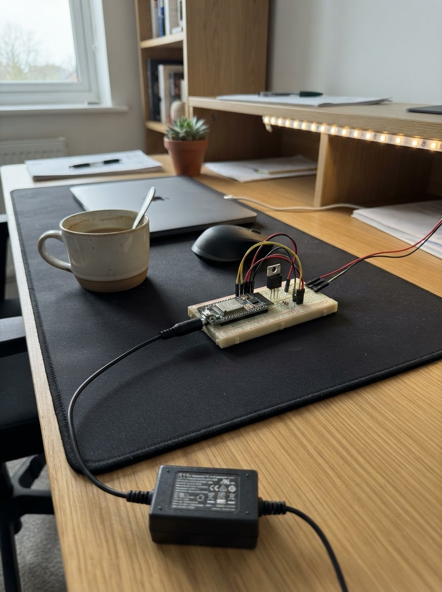
This project builds a simple LED strip dimmer using an ESP32 to control a 12 V non-addressable LED strip through a logic-level MOSFET. The IRLZ44N transistor acts as a high-current switch driven by PWM signals from the microcontroller, allowing smooth brightness control from the ESP32 without needing a separate dimming module.
The guide includes a complete wiring diagram showing how to connect the LED strip, power supply, and control circuitry, a full parts list with recommended suppliers, Arduino firmware ready to upload, and step-by-step assembly instructions. Builders will learn how to safely wire high-current loads to a microcontroller and implement PWM dimming for LED strips.
Wiring diagram

Gather all the parts
Assemble it in 4 steps
1. Prepare the separate power supplies
Leave both supplies unplugged while wiring. Use the D1 mini’s USB lead for the small controller board, and use a regulated 12 V DC supply rated at least 3 A for the LED strip. A 30 W strip uses about 2.5 A at 12 V.
- Use thicker wire, about 18–20 AWG, for the strip and 12 V supply wires so they do not get hot.
- If your supply has a barrel plug, use a matching screw-terminal barrel-jack adapter rather than cutting wires unless you know its polarity.
- Do not connect the 12 V supply positive wire to the D1 mini; 12 V can permanently damage the board.
- Do not work on the circuit while either power supply is plugged in.
2. Connect the LED strip and MOSFET power path
With the printed label facing you and the three legs pointing down, identify the IRLZ44N legs from left to right as GATE, DRAIN, and SOURCE. Connect LED strip +12V to the 12 V supply +12V (power). Connect LED strip GND to the MOSFET DRAIN, the centre leg (switched return). Connect the MOSFET SOURCE, the right leg, to the 12 V supply GND (ground).
- The strip’s + and − markings are normally printed beside its copper pads.
- Use a screw terminal, soldered joint, or other connection rated for at least 3 A; a thin solderless breadboard is not suitable for the strip-current path.
- Swapping the MOSFET’s drain and source can make the strip fail or heat the MOSFET.
- A loose high-current connection can get hot; stop immediately if a wire, connector, or MOSFET becomes too hot to touch.
3. Add the D1 mini control wires
Connect D5 on the D1 mini, which is GPIO14, to one lead of the 220 Ω resistor (signal). Connect the other 220 Ω resistor lead to the MOSFET GATE, the left leg (signal). Connect one lead of the 10 kΩ resistor to this same gate junction, and its other lead to D1 mini GND (ground). Connect D1 mini GND to the same shared ground as the MOSFET SOURCE and 12 V supply GND (ground).
- The 220 Ω and 10 kΩ resistors have no positive or negative end, so either direction is fine.
- The 10 kΩ resistor keeps the strip off while the D1 mini starts up or is unplugged.
- The D1 mini ground and the 12 V supply negative must be connected together or the dimming signal has no reference and the strip may behave unpredictably.
- Do not connect D5 directly to 12 V or to the LED strip positive terminal; that can damage the D1 mini.
4. Check, cool, and power the circuit
Before power is applied, check that the MOSFET flat face is oriented as described and that the LED strip negative goes to DRAIN, not directly to the supply negative. Attach a small heatsink to the MOSFET’s metal tab if the strip is near 30 W. Then connect the D1 mini by USB, plug in the 12 V supply, and use Schematik’s Deploy button to put the supplied firmware on the board.
- The provided firmware turns the strip fully on after startup; change the brightness constant later if you want a fixed dimmer setting.
- Test first with a short strip section if practical.
- The IRLZ44N metal tab is electrically connected to its DRAIN leg, so do not let the tab touch grounded metal or the heatsink unless the heatsink is electrically isolated.
- Unplug both supplies before changing any wire.
Review all connections
1. Connections between "supply_12v_3a" and "ESP32"
2. Connections between "led_strip_12v" and "ESP32"
3. Connections between "gate_resistor" and "ESP32"
4. Connections between "gate_pulldown" and "ESP32"
5. Connections between "mosfet_irlz44n" and "ESP32"
Deploy the firmware
#include <Arduino.h>
// 12 V LED-strip low-side driver for a WeMos D1 mini.
// D5 (GPIO14) drives the IRLZ44N gate through a 220 ohm resistor.

constexpr uint8_t LED_STRIP_GATE_PIN = 14;
constexpr uint16_t FULL_BRIGHTNESS = 1023;  // ESP8266 PWM range: 0 (off) to 1023 (full on)

void setup() {
  pinMode(LED_STRIP_GATE_PIN, OUTPUT);
  analogWriteRange(1023);
  analogWriteFreq(1000);  // 1 kHz: avoids visible flicker on most LED strips
  analogWrite(LED_STRIP_GATE_PIN, 0);  // keep the strip off during startup
  delay(250);
  analogWrite(LED_STRIP_GATE_PIN, FULL_BRIGHTNESS);  // turn the strip fully on
}

void loop() {
  // The strip stays fully on. Change FULL_BRIGHTNESS to a value from 0 to 1023 to set a fixed brightness.
}
Remix this project
Make it yours in one click
Open a full copy of this project in your own Schematik workspace — diagram, code, parts, and assembly steps included. Swap the sensor, add features, or redesign the whole thing with AI. The author's original stays untouched.