Community project
ESP32 LTE Smartphone
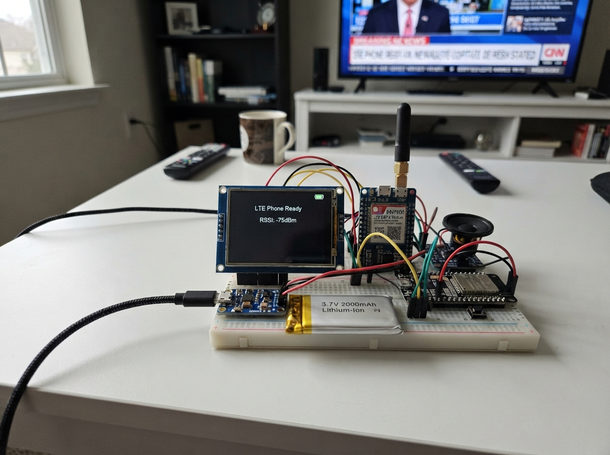
Build a functional LTE smartphone powered by an ESP32 microcontroller. This project combines a 3.3-inch touchscreen display, SIM7600 LTE modem, microphone, and speaker into a handheld device capable of cellular connectivity and voice communication. The guide includes a complete wiring diagram, detailed parts list, and step-by-step assembly instructions to integrate all components into a working prototype.
The firmware provided handles touchscreen input, modem communication, and UI rendering, giving builders a foundation to expand with SMS, calling, and custom applications. A rechargeable power system with charging module keeps the device running, while the home button provides hardware control. This project demonstrates how to combine industrial modules into a compact, battery-powered communication device.
Wiring diagram

Gather all the parts
Assemble it in 6 steps
1. Prepare the screen and controller
Place the ESP32-S3 board and the 2.8-inch screen on a non-metallic work surface. Connect the screen: VCC → 3V3 (power), GND → GND (ground), MOSI → GPIO11 (screen data), MISO → GPIO13 (touch data), SCK → GPIO12 (clock), TFT_CS → GPIO10 (screen select), TFT_DC → GPIO14 (screen command/data), TFT_RST → GPIO15 (screen reset), and TOUCH_CS → GPIO16 (touch select).
- Keep the screen wires short and label them before fitting a case.
- The screen and touch controller share the three MOSI, MISO, and SCK wires; that is normal.
- Make sure VCC and GND are not swapped — swapped power can damage the screen.
2. Connect the cellular modem and antenna
Attach the LTE antenna to the SIM7600E antenna socket before powering it. Insert an active SLT-Mobitel SIM in the modem. Connect modem VCC → 5V (power), GND → GND (ground), modem TXD → GPIO18 (messages from the modem), modem RXD → GPIO17 (messages to the modem), and PWRKEY → GPIO21 (modem on/off control).
- Keep the antenna away from the screen, battery, and long bundles of wires.
- Use a SIM7600E breakout that explicitly accepts 5 V input and 3.3 V UART logic.
- Never power the SIM7600E without its antenna fitted; cellular transmissions can stress the radio without a proper antenna.
- Do not try to draw modem power from the ESP32-S3 3V3 pin — cellular bursts need the separate 5 V supply.
3. Wire the speaker and microphone
Connect the amplifier: VIN → 5V (power), GND → GND (ground), BCLK → GPIO38 (sound clock), LRC → GPIO39 (sound timing), and DIN → GPIO41 (sound data). Connect amplifier SPK+ to the speaker POS terminal and SPK- to the speaker NEG terminal. Connect the microphone: VDD → 3V3 (power), GND → GND (ground), SD → GPIO40 (microphone data), SCK → GPIO47 (microphone clock), WS → GPIO48 (microphone timing), and L/R → GND (left-channel selection).
- Use a small 8-ohm speaker and mount it so its cone is not blocked.
- The amplifier speaker terminals are a pair; neither speaker wire goes to GND.
- Do not connect either SPK terminal to ground — it can damage the amplifier.
4. Add the home button
Connect one leg of the momentary push button to GPIO42 (button signal) and the other leg to GND (ground). A quick press returns the display to its home screen.
- On a four-leg tactile switch, use two legs on opposite sides, not the two legs on the same connected side.
- Do not connect the button to 5 V; the ESP32-S3 pins use 3.3 V signals.
5. Build the rechargeable power section
Connect battery BAT+ → charger B+ and battery BAT- → charger B-. Connect charger OUT+ → boost converter VIN+ and charger OUT- → boost converter VIN-. Set the boost converter to a steady 5.0 V with a multimeter before connecting it. Then connect boost VOUT+ → the project 5V rail and VOUT- → GND. The 5V rail powers the SIM7600E and amplifier; all grounds join together.
- Use a protected 3.7 V lithium battery pack with its correct two-wire connector.
- Charge through the TP4056 input only, using its USB input.
- Set and measure the boost output before attaching the ESP32-S3 or modem — a setting above 5 V can damage them.
- Never short, crush, puncture, or charge an unprotected lithium cell; a damaged battery can overheat or catch fire.
6. Power up and fit the handheld case
With power off, inspect every power and ground wire once more. Place the antenna where it has clear space, then secure the boards, battery, speaker, microphone, and screen in a non-metal case. Plug the ESP32-S3 into USB for programming while leaving the cellular power wiring connected. The home screen should appear after deployment.
- Leave access to the TP4056 charging connector and the ESP32-S3 USB-C connector.
- Test the screen, then the modem response, before permanently closing the case.
- Do not enclose the LTE antenna inside metal or directly against the battery; signal strength will be poor.
Review all connections
1. Connections between "tft_touch_1" and "ESP32"
2. Connections between "lte_modem_1" and "ESP32"
3. Connections between "mic_1" and "ESP32"
4. Connections between "audio_amp_1" and "ESP32"
5. Connections between "power_button_1" and "ESP32"
6. Connections between "battery_1" and "ESP32"
7. Connections between "charger_1" and "ESP32"
8. Connections between "boost_5v_1" and "ESP32"
Deploy the firmware
#include <Arduino.h>
#include <SPI.h>
#include <Adafruit_GFX.h>
#include <Adafruit_ILI9341.h>
#include <XPT2046_Touchscreen.h>


// Forward declarations
void drawHome();
void drawModemPage();
void queryModem();
void showModemPage();
void handleTouch();
void handleButton();

constexpr int TFT_CS_PIN = 10;
constexpr int TFT_DC_PIN = 14;
constexpr int TFT_RST_PIN = 15;
constexpr int TOUCH_CS_PIN = 16;
constexpr int MODEM_RX_PIN = 18;
constexpr int MODEM_TX_PIN = 17;
constexpr int MODEM_PWRKEY_PIN = 21;
constexpr int BUTTON_PIN = 42;

Adafruit_ILI9341 tft(TFT_CS_PIN, TFT_DC_PIN, TFT_RST_PIN);
XPT2046_Touchscreen touch(TOUCH_CS_PIN);
HardwareSerial modem(1);

const uint16_t BACKGROUND = ILI9341_BLACK;
const uint16_t PANEL = ILI9341_DARKCYAN;
const uint16_t ACCENT = ILI9341_CYAN;
const uint16_t TEXT = ILI9341_WHITE;

bool modemPage = false;
bool lastButton = HIGH;
uint32_t lastButtonChange = 0;
uint32_t lastTouch = 0;
String modemLine = "Starting modem...";

void drawHome() {
  tft.fillScreen(BACKGROUND);
  tft.fillRect(0, 0, 320, 38, PANEL);
  tft.setTextColor(TEXT, PANEL);
  tft.setTextSize(2);
  tft.setCursor(10, 11);
  tft.print("Sri Lanka Phone");

  tft.drawRoundRect(12, 58, 296, 70, 8, ACCENT);
  tft.setTextColor(TEXT, BACKGROUND);
  tft.setTextSize(2);
  tft.setCursor(28, 78);
  tft.print("Messages");
  tft.setTextSize(1);
  tft.setCursor(28, 105);
  tft.print("SMS modem link ready");

  tft.drawRoundRect(12, 145, 296, 70, 8, ACCENT);
  tft.setTextSize(2);
  tft.setCursor(28, 165);
  tft.print("Mobile network");
  tft.setTextSize(1);
  tft.setCursor(28, 192);
  tft.print("Tap for modem status");

  tft.setTextColor(ILI9341_LIGHTGREY, BACKGROUND);
  tft.setCursor(14, 224);
  tft.print("Side button returns here");
}

void drawModemPage() {
  tft.fillScreen(BACKGROUND);
  tft.fillRect(0, 0, 320, 38, PANEL);
  tft.setTextColor(TEXT, PANEL);
  tft.setTextSize(2);
  tft.setCursor(10, 11);
  tft.print("Network status");
  tft.setTextColor(TEXT, BACKGROUND);
  tft.setTextSize(1);
  tft.setCursor(14, 62);
  tft.print("SIM7600 AT response:");
  tft.fillRoundRect(14, 80, 292, 88, 6, ILI9341_NAVY);
  tft.setCursor(22, 94);
  tft.print(modemLine);
  tft.setCursor(14, 198);
  tft.setTextColor(ILI9341_YELLOW, BACKGROUND);
  tft.print("Voice calls require SLT-Mobitel VoLTE");
  tft.setCursor(14, 215);
  tft.print("provisioning on your SIM.");
}

void queryModem() {
  modemLine = "No reply yet";
  while (modem.available()) modem.read();
  modem.println("AT");
  uint32_t started = millis();
  String reply;
  while (millis() - started < 1200) {
    while (modem.available()) {
      char c = static_cast<char>(modem.read());
      if (c != '\r' && c != '\n') reply += c;
    }
  }
  if (reply.length() > 0) modemLine = reply.substring(0, 34);
  if (modemPage) drawModemPage();
}

void showModemPage() {
  modemPage = true;
  drawModemPage();
  queryModem();
}

void handleTouch() {
  if (!touch.touched() || millis() - lastTouch < 250) return;
  TS_Point p = touch.getPoint();
  lastTouch = millis();
  int screenY = map(p.x, 200, 3800, 0, 320);
  if (!modemPage && screenY > 135) showModemPage();
  else if (modemPage) {
    modemPage = false;
    drawHome();
  }
}

void handleButton() {
  bool state = digitalRead(BUTTON_PIN);
  if (state != lastButton && millis() - lastButtonChange > 35) {
    lastButtonChange = millis();
    lastButton = state;
    if (state == LOW) {
      modemPage = false;
      drawHome();
    }
  }
}

void setup() {
  pinMode(BUTTON_PIN, INPUT_PULLUP);
  pinMode(MODEM_PWRKEY_PIN, OUTPUT);
  digitalWrite(MODEM_PWRKEY_PIN, HIGH);

  SPI.begin(12, 13, 11, TFT_CS_PIN);
  tft.begin();
  tft.setRotation(1);
  touch.begin();
  touch.setRotation(1);
  drawHome();

  modem.begin(115200, SERIAL_8N1, MODEM_RX_PIN, MODEM_TX_PIN);
  delay(100);
  queryModem();
}

void loop() {
  handleTouch();
  handleButton();
}
Remix this project
Make it yours in one click
Open a full copy of this project in your own Schematik workspace — diagram, code, parts, and assembly steps included. Swap the sensor, add features, or redesign the whole thing with AI. The author's original stays untouched.
Related projects

Create A Complete Electrical Schematic Esp32 Sma
ESP32 · September 17, 2026Ayansh Agrawal
ESP32 Kare Ekran Projeleri
ESP32 · September 16, 2026Seref Ai
Component Qty --------------------------- ------
ESP32 · September 16, 2026Yathartha Chakrawal