Community project
ESP32 Music Player
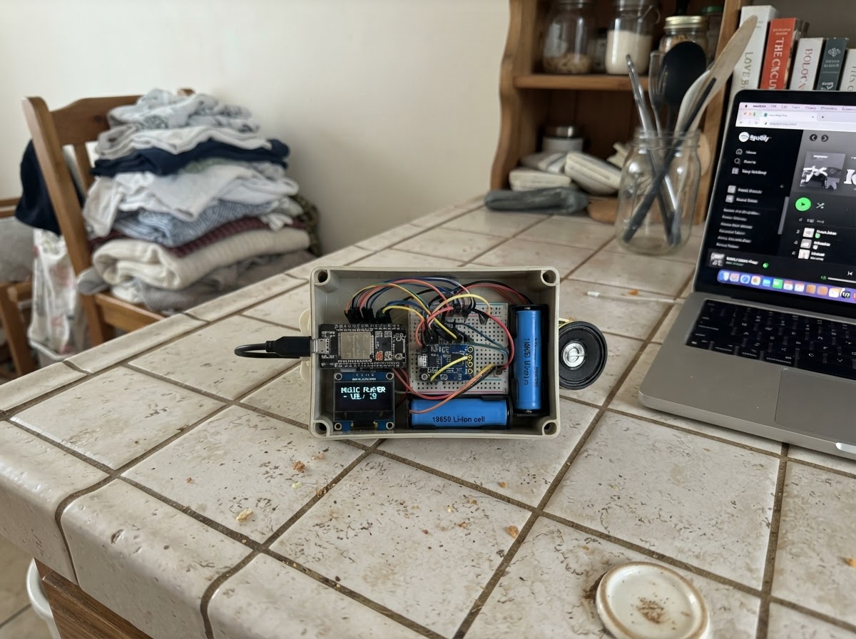
Build a portable Bluetooth music player powered by an ESP32 that streams audio wirelessly from your phone or tablet. The MAX98357A Class-D amplifier drives a speaker with clean, efficient mono sound, while an SSD1306 OLED display shows playback status. A rechargeable 18650 battery with charging module and 5V boost converter provides hours of cordless listening.
This guide includes a complete wiring diagram, parts list with sourcing tips, and ready-to-flash Arduino firmware with Bluetooth A2DP support. Follow the step-by-step assembly instructions to wire the power supply, connect the I2S audio path, and integrate the display. Once programmed, the player pairs instantly with any Bluetooth device and begins streaming.
Wiring diagram

Gather all the parts
Assemble it in 5 steps
1. Prepare the battery supply
Use one protected 3.7 V 18650 cell in a proper insulated holder. Connect battery_1 positive to charger_1 B+ and battery_1 negative to charger_1 B-.
- Use a protected cell and an insulated holder; observe the + and − marks.
- Never short, puncture, solder directly to, or charge an unprotected lithium-ion cell.
2. Wire the charger and 5 V converter
Connect charger_1 OUT+ to boost_1 IN+ and charger_1 OUT− to boost_1 IN−. Before connecting the ESP32, power the charger from its USB charging connector and adjust the MT3608 output between boost_1 OUT+ and OUT− to exactly 5.0 V using a multimeter.
- The TP4056 IN pads are for charging input only; use its protected OUT pads for the player load.
- Do not connect the battery or ESP32 until the boost output has been measured and set to 5.0 V. Higher voltage can damage the ESP32 and OLED.
3. Connect the ESP32, amplifier, and speaker
Connect boost_1 OUT+ to the ESP32 VIN/5V pin and boost_1 OUT− to ESP32 GND. Connect amp_1 VIN to ESP32 VIN/5V, amp_1 GND to ESP32 GND, BCLK to GPIO26, LRC to GPIO25, and DIN to GPIO27. Connect amp_1 SPK+ to speaker_1 POS and amp_1 SPK− to speaker_1 NEG.
- Keep the amplifier-to-speaker wires short and use a speaker rated 8 Ω and 1–3 W.
- SPK− is an amplified output, not ground. Connect the speaker only between SPK+ and SPK−.
4. Connect the status OLED
Connect oled_1 VCC to ESP32 3V3 and oled_1 GND to ESP32 GND. Connect oled_1 SDA to GPIO21 and oled_1 SCL to GPIO22.
- This design expects the usual SSD1306 I2C address 0x3C.
- The OLED uses 3.3 V logic and supply in this build.
- Do not connect the OLED VCC to the 5 V rail.
5. Power and charge safely
Turn the portable player on by connecting the charged battery. Charge it by supplying 5 V USB to charger_1's input; the TP4056 handles battery charging. The ESP32 will advertise as Schematik Music Player for Bluetooth pairing.
- A 2500 mAh cell is estimated at roughly 2.8 hours at a typical loud playback load; runtime varies with volume.
- Use Schematik’s Deploy button to flash the firmware.
- Do not leave lithium-ion charging unattended or charge inside a sealed enclosure. The MT3608 and amplifier need airflow at high volume.
Review all connections
1. Connections between "amp_1" and "ESP32"
2. Connections between "oled_1" and "ESP32"
3. Connections between "battery_1" and "ESP32"
4. Connections between "charger_1" and "ESP32"
5. Connections between "boost_1" and "ESP32"
Deploy the firmware
#include <Arduino.h>
#include <Wire.h>
#include <Adafruit_GFX.h>
#include <Adafruit_SSD1306.h>
#include <BluetoothA2DPSink.h>
#include <driver/i2s.h>


// Forward declarations
void showStatus(const char *line1, const char *line2);

constexpr int I2S_BCLK_PIN = 26;
constexpr int I2S_LRC_PIN = 25;
constexpr int I2S_DOUT_PIN = 27;
constexpr int OLED_SDA_PIN = 21;
constexpr int OLED_SCL_PIN = 22;
constexpr uint8_t OLED_ADDRESS = 0x3C;

Adafruit_SSD1306 display(128, 64, &Wire, -1);
BluetoothA2DPSink a2dpSink;

i2s_config_t i2sConfig = {
  .mode = static_cast<i2s_mode_t>(I2S_MODE_MASTER | I2S_MODE_TX),
  .sample_rate = 44100,
  .bits_per_sample = I2S_BITS_PER_SAMPLE_16BIT,
  .channel_format = I2S_CHANNEL_FMT_RIGHT_LEFT,
  .communication_format = I2S_COMM_FORMAT_STAND_I2S,
  .intr_alloc_flags = ESP_INTR_FLAG_LEVEL1,
  .dma_buf_count = 8,
  .dma_buf_len = 64,
  .use_apll = false,
  .tx_desc_auto_clear = true,
  .fixed_mclk = 0
};

i2s_pin_config_t i2sPins = {
  .bck_io_num = I2S_BCLK_PIN,
  .ws_io_num = I2S_LRC_PIN,
  .data_out_num = I2S_DOUT_PIN,
  .data_in_num = I2S_PIN_NO_CHANGE
};

void showStatus(const char *line1, const char *line2) {
  display.clearDisplay();
  display.setTextColor(SSD1306_WHITE);
  display.setTextSize(1);
  display.setCursor(0, 0);
  display.println(F("SCHEMATIK PLAYER"));
  display.drawFastHLine(0, 12, 128, SSD1306_WHITE);
  display.setTextSize(2);
  display.setCursor(0, 22);
  display.println(line1);
  display.setTextSize(1);
  display.setCursor(0, 50);
  display.println(line2);
  display.display();
}

void setup() {
  Serial.begin(115200);
  Wire.begin(OLED_SDA_PIN, OLED_SCL_PIN);
  if (display.begin(SSD1306_SWITCHCAPVCC, OLED_ADDRESS)) {
    showStatus("Bluetooth", "Pair: Schematik Music Player");
  }

  a2dpSink.set_i2s_config(i2sConfig);
  a2dpSink.set_pin_config(i2sPins);
  a2dpSink.start("Schematik Music Player");
  Serial.println("Bluetooth music player ready. Pair with: Schematik Music Player");
}

void loop() {
  delay(1000);
}
Remix this project
Make it yours in one click
Open a full copy of this project in your own Schematik workspace — diagram, code, parts, and assembly steps included. Swap the sensor, add features, or redesign the whole thing with AI. The author's original stays untouched.