Community project
ESP32 Parking Distance Alert
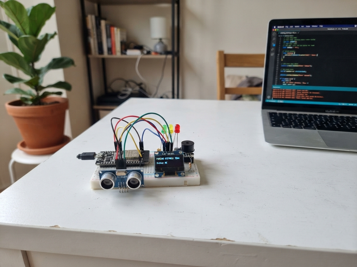
This project builds a parking distance alert system using an ESP32 microcontroller and ultrasonic sensor to warn drivers as they approach an obstacle. The system displays real-time distance on an OLED screen and provides visual and audio feedback through color-coded LEDs and a buzzer that accelerates as the obstacle gets closer.
The guide includes a complete wiring diagram, parts list, and ready-to-upload firmware. Assembly takes about 30 minutes and involves connecting the HC-SR04P distance sensor, mounting the OLED display, wiring the three indicator LEDs with current-limiting resistors, and adding the piezo buzzer. Testing against a wall verifies all distance thresholds and alert outputs are working correctly.
Wiring diagram

Gather all the parts
Assemble it in 4 steps
1. Wire the distance sensor
Connect the HC-SR04P VCC and GND to the ESP32 3V3 and GND rails, then connect TRIG to GPIO27 and ECHO to GPIO26.
- Use the HC-SR04P 3.3V-compatible module, not a 5V-only HC-SR04, unless you add proper level shifting.
- Do not connect a 5V echo signal directly to an ESP32 GPIO.
2. Add the display
Connect the SSD1306 OLED to the same 3V3 and GND rails, with SDA on GPIO21 and SCL on GPIO22.
- If the OLED stays blank, check whether your module uses address 0x3C or 0x3D.
3. Add the warning outputs
Connect the green LED to GPIO14, yellow LED to GPIO12, red LED to GPIO13, and the passive buzzer signal pin to GPIO25. Each LED should use a current-limiting resistor.
- Place the LEDs left to right as green, yellow, red so the warning pattern reads naturally.
- Do not drive bare LEDs directly from GPIO without resistors.
4. Upload and test against a wall
Upload the sketch, aim the sensor at a flat surface, and move it from about one metre away to the stop zone. The OLED, LEDs, and buzzer should change together.
- Cardboard, foam board, or a book makes a better test target than a thin chair leg.
- This is a learning aid, not a safety-rated vehicle parking system.
Review all connections
1. Connections between "hc-sr04p-ultrasonic-sensor_0" and "ESP32"
2. Connections between "ssd1306-oled_0" and "ESP32"
3. Connections between "green-led_0" and "ESP32"
4. Connections between "yellow-led_0" and "ESP32"
5. Connections between "red-led_0" and "ESP32"
6. Connections between "passive-buzzer_0" and "ESP32"
7. Connections between "esp32-ultrasonic-parking-sensor-220-ohm-resistor-1" and "ESP32"
Deploy the firmware
#include <Wire.h>
#include <Adafruit_GFX.h>
#include <Adafruit_SSD1306.h>

#define TRIG_PIN 27
#define ECHO_PIN 26
#define GREEN_LED_PIN 14
#define YELLOW_LED_PIN 12
#define RED_LED_PIN 13
#define BUZZER_PIN 25
#define SDA_PIN 21
#define SCL_PIN 22
#define SCREEN_WIDTH 128
#define SCREEN_HEIGHT 64

const int SAFE_DISTANCE_CM = 70;
const int CAUTION_DISTANCE_CM = 35;
const int STOP_DISTANCE_CM = 18;

Adafruit_SSD1306 display(SCREEN_WIDTH, SCREEN_HEIGHT, &Wire, -1);
float smoothedDistance = 100;
unsigned long lastBeepMs = 0;
bool buzzerOn = false;

float readDistanceCm() {
  digitalWrite(TRIG_PIN, LOW);
  delayMicroseconds(2);
  digitalWrite(TRIG_PIN, HIGH);
  delayMicroseconds(10);
  digitalWrite(TRIG_PIN, LOW);

  unsigned long duration = pulseIn(ECHO_PIN, HIGH, 30000);
  if (duration == 0) return smoothedDistance;
  return duration / 58.0;
}

void setOutputs(float distanceCm) {
  bool safe = distanceCm > SAFE_DISTANCE_CM;
  bool caution = distanceCm <= SAFE_DISTANCE_CM && distanceCm > CAUTION_DISTANCE_CM;
  bool warning = distanceCm <= CAUTION_DISTANCE_CM;

  digitalWrite(GREEN_LED_PIN, safe ? HIGH : LOW);
  digitalWrite(YELLOW_LED_PIN, caution ? HIGH : LOW);
  digitalWrite(RED_LED_PIN, warning ? HIGH : LOW);

  if (!warning) {
    noTone(BUZZER_PIN);
    buzzerOn = false;
    return;
  }

  int interval = distanceCm <= STOP_DISTANCE_CM ? 120 : 320;
  if (millis() - lastBeepMs > interval) {
    lastBeepMs = millis();
    buzzerOn = !buzzerOn;
    if (buzzerOn) tone(BUZZER_PIN, distanceCm <= STOP_DISTANCE_CM ? 1800 : 1200);
    else noTone(BUZZER_PIN);
  }
}

void drawDisplay(float distanceCm) {
  display.clearDisplay();
  display.setTextColor(SSD1306_WHITE);
  display.setTextSize(1);
  display.setCursor(0, 0);
  display.println("Parking sensor");
  display.setTextSize(2);
  display.setCursor(0, 18);
  display.print(distanceCm, 0);
  display.println(" cm");
  display.setTextSize(1);
  display.setCursor(0, 48);
  if (distanceCm <= STOP_DISTANCE_CM) display.println("STOP");
  else if (distanceCm <= CAUTION_DISTANCE_CM) display.println("Slow down");
  else if (distanceCm <= SAFE_DISTANCE_CM) display.println("Getting close");
  else display.println("Clear");
  display.display();
}

void setup() {
  pinMode(TRIG_PIN, OUTPUT);
  pinMode(ECHO_PIN, INPUT);
  pinMode(GREEN_LED_PIN, OUTPUT);
  pinMode(YELLOW_LED_PIN, OUTPUT);
  pinMode(RED_LED_PIN, OUTPUT);
  pinMode(BUZZER_PIN, OUTPUT);

  Wire.begin(SDA_PIN, SCL_PIN);
  display.begin(SSD1306_SWITCHCAPVCC, 0x3C);
  display.clearDisplay();
  display.display();
}

void loop() {
  float reading = readDistanceCm();
  smoothedDistance = (smoothedDistance * 0.75) + (reading * 0.25);
  setOutputs(smoothedDistance);
  drawDisplay(smoothedDistance);
  delay(80);
}
Remix this project
Make it yours in one click
Open a full copy of this project in your own Schematik workspace — diagram, code, parts, and assembly steps included. Swap the sensor, add features, or redesign the whole thing with AI. The author's original stays untouched.