Community project
Hall-Effect RPM Monitor
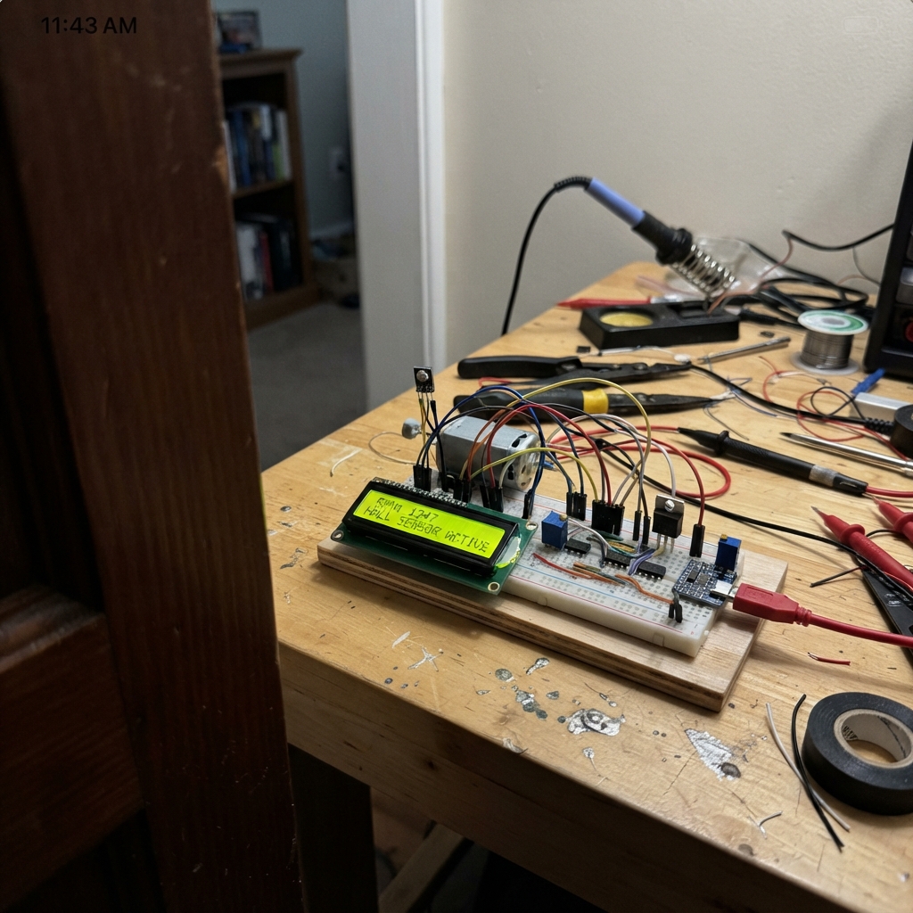
This project builds a real-time RPM monitor for a brushed DC motor using a Hall-effect sensor to detect shaft rotation. The ESP32 reads the sensor pulses, calculates RPM with noise filtering, and displays the result on a 16×2 LCD while a potentiometer lets you adjust motor speed via PWM control.
The guide provides a complete wiring diagram, parts list, and step-by-step assembly instructions covering sensor placement, op-amp signal conditioning, motor driver setup, and firmware configuration. By the end, you'll have a working tachometer that measures motor speed accurately and handles electrical noise rejection.
Wiring diagram

Gather all the parts
Assemble it in 7 steps
1. Place the shaft magnet and Hall sensor
Fix one small diametrically magnetized magnet to the motor shaft. Hold the flat face of hall_ss49e 2–5 mm from the magnet’s path, with the sensor’s marked face aimed at the magnet. Wire VCC → 5 V (power), GND → GND (ground), and OUT → the 24 kΩ resistor r_gain_in (signal).
- Turn the shaft slowly by hand first; reversing the sensor face reverses the waveform but does not damage it.
- Keep the magnet firmly attached: a loose magnet can be thrown from the spinning shaft.
2. Build the Hall amplifier
Power opamp_mcp6002 with VDD → 5 V (power) and VSS → GND (ground). Make the 2.5 V reference from r_vq_top and r_vq_bottom: 5 V → r_vq_top → shared midpoint → r_vq_bottom → GND. Connect r_gain_in from Hall OUT to A_IN+, r_gain_ref from the 1.65 V midpoint to A_IN+, r_gain_in_vq from the 2.5 V midpoint to A_IN−, and r_gain_fb from A_OUT back to A_IN−.
- Use four separate 1% resistors for the 24 kΩ/56 kΩ matched ratios; do not replace them with series or parallel combinations.
- Make sure the 5 V and GND pins are not swapped — swapped power can damage the amplifier.
3. Make the clean 3.3 V pulse
Power comparator_mcp6561 from 3V3 and GND. Join r_schmitt_in from the amplifier output to IN+, and r_schmitt_fb from OUT back to IN+. Connect IN− to the 1.65 V midpoint made by r_vref_top and r_vref_bottom. Connect comparator OUT → ESP32 GPIO27 (speed signal).
- The comparator output is already a safe 0–3.3 V signal for the ESP32; never connect the 5 V Hall output directly to GPIO27.
- Do not omit the common ground: without it the pulse has no shared voltage reference and the speed reading will jump.
4. Wire the motor switch
Connect motor_5v M+ → 5 V (power) and M− → motor_mosfet DRAIN (switched return). Connect motor_mosfet SOURCE → GND (ground). Put flyback_1n5819 across the motor: cathode → 5 V and anode → M−. Connect ESP32 GPIO25 through r_gate to the MOSFET gate, and r_gate_pull from the same gate to GND.
- The diode’s striped end is its cathode; it goes to the motor’s 5 V side.
- A reversed flyback diode shorts the supply when the motor turns on and can damage the adapter, diode, or wiring.
5. Wire the speed knob
Connect pot_10k END_A → 3V3 (power), END_B → GND (ground), and the middle WIPER → ESP32 GPIO34 (signal). Turning the knob changes the motor PWM command.
- If clockwise rotation lowers the speed, swap the two outside potentiometer connections.
- Use 3.3 V, not 5 V, on the potentiometer: GPIO34 must never receive more than 3.3 V.
6. Connect the LCD safely
Power lcd from 5 V and GND. Put i2c_level_shifter between it and the ESP32: shifter LV → 3V3 (power), HV → 5 V (power), GND → GND (ground), LV_SDA → GPIO21 (data), LV_SCL → GPIO22 (data), and connect LCD SDA/SCL to the matching HV_SDA/HV_SCL pins.
- The level-shifter is necessary because the LCD’s pull-up resistors use 5 V while the ESP32 pins only accept 3.3 V.
- Do not connect the LCD’s 5 V SDA or SCL wires directly to the ESP32 — 5 V can damage its inputs.
7. Apply power and check the motion
Connect supply_5v to the 5 V rail and GND rail. Plug the ESP32 into USB so it has its normal board power, while keeping all grounds joined. The screen should show motor duty and measured RPM; turn the knob slowly and watch the reading change.
- Start at a low knob setting and keep fingers, loose wires, and clothing away from the rotating shaft.
- Use a supply that can provide the motor’s stall current; an undersized supply can reset the ESP32 or overheat.
Review all connections
1. Connections between "supply_5v" and "ESP32"
2. Connections between "hall_ss49e" and "ESP32"
3. Connections between "opamp_mcp6002" and "ESP32"
4. Connections between "r_gain_in_vq" and "ESP32"
5. Connections between "r_vq_top" and "ESP32"
6. Connections between "r_vq_bottom" and "ESP32"
7. Connections between "r_gain_fb" and "ESP32"
8. Connections between "r_gain_ref" and "ESP32"
9. Connections between "r_vref_top" and "ESP32"
10. Connections between "r_vref_bottom" and "ESP32"
11. Connections between "comparator_mcp6561" and "ESP32"
12. Connections between "r_schmitt_in" and "ESP32"
13. Connections between "r_schmitt_fb" and "ESP32"
14. Connections between "pot_10k" and "ESP32"
15. Connections between "r_gate" and "ESP32"
16. Connections between "r_gate_pull" and "ESP32"
17. Connections between "motor_mosfet" and "ESP32"
18. Connections between "motor_5v" and "ESP32"
19. Connections between "flyback_1n5819" and "ESP32"
20. Connections between "i2c_level_shifter" and "ESP32"
21. Connections between "lcd" and "ESP32"
Deploy the firmware
#include <Arduino.h>
#include <Wire.h>
#include <LiquidCrystal_I2C.h>

constexpr uint8_t HALL_EDGE_PIN = 27;
constexpr uint8_t POT_PIN = 34;
constexpr uint8_t MOTOR_PWM_PIN = 25;
constexpr uint8_t I2C_SDA_PIN = 21;
constexpr uint8_t I2C_SCL_PIN = 22;
constexpr uint8_t PULSES_PER_REV = 1;
constexpr uint32_t PWM_FREQUENCY_HZ = 20000;
constexpr uint8_t PWM_BITS = 10;
constexpr uint16_t PWM_MAX = (1U << PWM_BITS) - 1U;
constexpr uint32_t STOP_TIMEOUT_US = 2500000UL;
constexpr uint8_t PERIOD_AVERAGES = 8;

LiquidCrystal_I2C lcd(0x27, 16, 2);

volatile uint32_t lastEdgeUs = 0;
volatile uint32_t capturedPeriodUs = 0;
volatile bool periodReady = false;

uint32_t periodSamples[PERIOD_AVERAGES] = {0};
uint8_t sampleCount = 0;
uint8_t sampleIndex = 0;
uint32_t lastScreenUpdateMs = 0;
float shownRpm = -1.0f;
int shownDuty = -1;

void IRAM_ATTR hallEdgeISR() {
  const uint32_t nowUs = micros();
  if (lastEdgeUs != 0) {
    const uint32_t candidateUs = nowUs - lastEdgeUs;
    // Reject implausibly short pulses caused by electrical noise.
    if (candidateUs >= 1000UL) {
      capturedPeriodUs = candidateUs;
      periodReady = true;
    }
  }
  lastEdgeUs = nowUs;
}

float averagedRpm() {
  if (sampleCount == 0) return 0.0f;
  uint64_t sumUs = 0;
  for (uint8_t i = 0; i < sampleCount; ++i) sumUs += periodSamples[i];
  const float averagePeriodUs = static_cast<float>(sumUs) / sampleCount;
  if (averagePeriodUs <= 0.0f) return 0.0f;
  return 60000000.0f / (averagePeriodUs * PULSES_PER_REV);
}

float roundToHalfRpm(float value) {
  return roundf(value * 2.0f) / 2.0f;
}

void drawScreen(float rpm, int dutyPercent) {
  lcd.setCursor(0, 0);
  lcd.print("RPM: ");
  lcd.print(rpm, 1);
  lcd.print("       ");
  lcd.setCursor(0, 1);
  lcd.print("Motor: ");
  lcd.print(dutyPercent);
  lcd.print("%       ");
}

void setup() {
  pinMode(HALL_EDGE_PIN, INPUT);
  pinMode(POT_PIN, INPUT);
  Wire.begin(I2C_SDA_PIN, I2C_SCL_PIN);
  lcd.init();
  lcd.backlight();
  lcd.clear();
  lcd.setCursor(0, 0);
  lcd.print("Hall RPM meter");
  lcd.setCursor(0, 1);
  lcd.print("Starting...");

  ledcAttach(MOTOR_PWM_PIN, PWM_FREQUENCY_HZ, PWM_BITS);
  ledcWrite(MOTOR_PWM_PIN, 0);
  attachInterrupt(digitalPinToInterrupt(HALL_EDGE_PIN), hallEdgeISR, RISING);
}

void loop() {
  const int potRaw = analogRead(POT_PIN);
  const uint16_t pwmDuty = map(potRaw, 0, 4095, 0, PWM_MAX);
  const int dutyPercent = static_cast<int>((100UL * pwmDuty + PWM_MAX / 2) / PWM_MAX);
  ledcWrite(MOTOR_PWM_PIN, pwmDuty);

  if (periodReady) {
    noInterrupts();
    const uint32_t periodUs = capturedPeriodUs;
    periodReady = false;
    interrupts();
    periodSamples[sampleIndex] = periodUs;
    sampleIndex = (sampleIndex + 1) % PERIOD_AVERAGES;
    if (sampleCount < PERIOD_AVERAGES) ++sampleCount;
  }

  float rpm = 0.0f;
  const uint32_t edgeAgeUs = micros() - lastEdgeUs;
  if (lastEdgeUs != 0 && edgeAgeUs <= STOP_TIMEOUT_US) rpm = roundToHalfRpm(averagedRpm());

  const uint32_t nowMs = millis();
  if (nowMs - lastScreenUpdateMs >= 200 && (rpm != shownRpm || dutyPercent != shownDuty)) {
    drawScreen(rpm, dutyPercent);
    shownRpm = rpm;
    shownDuty = dutyPercent;
    lastScreenUpdateMs = nowMs;
  }
}
Remix this project
Make it yours in one click
Open a full copy of this project in your own Schematik workspace — diagram, code, parts, and assembly steps included. Swap the sensor, add features, or redesign the whole thing with AI. The author's original stays untouched.