Community project
ESP32 Robotic Arm Control
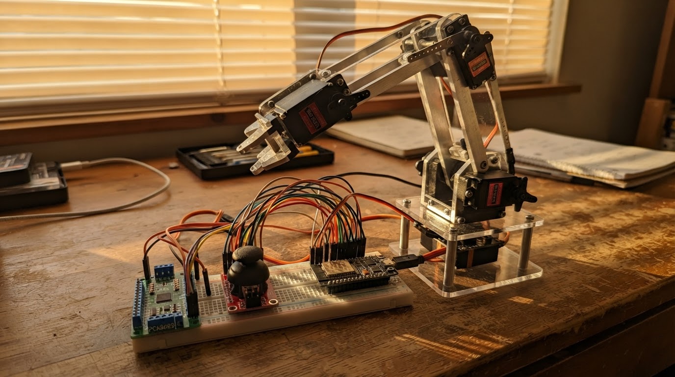
This guide builds a four-joint robotic arm controlled by an ESP32 microcontroller. The arm uses MG996R servo motors for each joint (base rotation, shoulder, elbow, and gripper), coordinated through a PCA9685 PWM servo driver that handles precise timing for all servos simultaneously.
Readers will receive a complete wiring diagram showing connections between the ESP32, PCA9685 driver, joystick module, and servo motors, along with a full parts list, calibration firmware, and step-by-step assembly instructions. The dual-axis joystick provides intuitive control over multiple arm joints, with the firmware handling servo angle mapping and movement constraints.
Wiring diagram

Gather all the parts
Assemble it in 5 steps
1. Lắp khung khi chưa cấp điện
Lắp đế, vai, khuỷu và kẹp theo bộ bracket; đặt từng servo về gần giữa hành trình bằng cách xoay nhẹ horn trước khi bắt vít. Không ép servo chạm điểm chặn cơ khí vì bánh răng có thể hỏng.
- Dùng bạc đạn hoặc trục phụ cho khớp vai nếu khung dài; không để toàn bộ tải treo trên trục servo.
- Để cánh tay ngắn và nhẹ ở bản đầu: đoạn vai và khuỷu khoảng 10–15 cm là hợp lý.
- Không cấp điện khi tay bạn đang giữ horn hoặc cơ cấu đang kẹt — servo có thể giật mạnh.
2. Nối mạch điều khiển servo
Nối PCA9685 VCC → 3V3 của ESP32 (nguồn logic), GND → GND của ESP32 (mass chung), SDA → GPIO21 (dữ liệu) và SCL → GPIO22 (xung nhịp). Cắm dây tín hiệu của servo đế, vai, khuỷu và kẹp lần lượt vào PWM0, PWM1, PWM2, PWM3 (tín hiệu).
- Dây servo thường là nâu/đen = GND, đỏ = 6 V, cam/vàng/trắng = tín hiệu.
- Gắn tụ điện phân 1000–2200 µF, điện áp định mức ít nhất 10 V, ngay trên V+ và GND của PCA9685 để giảm sụt áp khi servo khởi động.
- Không cắm dây đỏ của servo vào chân 3V3 hoặc 5V của ESP32 — dòng lớn có thể làm reset hoặc hỏng bo mạch.
- Để ý cực âm của tụ: vạch sọc trên thân tụ phải về GND; lắp ngược tụ có thể làm tụ nóng hoặc hỏng.
3. Nối hai cần điều khiển
Cấp mỗi joystick bằng 3V3 và GND của ESP32. Joystick trái: VRx → GPIO34 (tín hiệu xoay đế), VRy → GPIO35 (tín hiệu vai). Joystick phải: VRx → GPIO36 (tín hiệu khuỷu), VRy → GPIO39 (tín hiệu kẹp).
- Cấp joystick bằng 3,3 V để tín hiệu analog không vượt quá mức ESP32 chịu được.
- Các GPIO34, GPIO35, GPIO36 và GPIO39 chỉ dùng làm đầu vào, rất phù hợp để đọc joystick.
- Không cấp joystick 5 V rồi đưa VRx/VRy thẳng vào ESP32 — mức điện áp cao có thể làm hỏng chân đọc tín hiệu.
4. Đấu nguồn servo và mass chung
Nối cực dương của nguồn DC ổn áp 6 V, tối thiểu 10 A, vào chân V+ của PCA9685 (nguồn servo). Nối cực âm nguồn 6 V vào thanh GND của PCA9685 và nối thanh GND này với GND của ESP32 (mass chung). ESP32 lấy điện riêng qua cổng USB.
- Đặt cầu chì 7,5–10 A và công tắc ở dây dương 6 V trước PCA9685.
- Dùng dây nguồn đủ to, khoảng AWG18–20, từ nguồn tới PCA9685; dây jumper mảnh chỉ phù hợp với tín hiệu.
- Chỉ dùng bộ nguồn DC 6 V cách ly, có vỏ kín; không tự đấu điện lưới 220 V vào nguồn trần.
- Không nối chung mass thì tín hiệu servo không có mốc tham chiếu và cánh tay có thể rung hoặc chạy sai.
5. Cấp điện và căn vị trí ban đầu
Đặt cánh tay trên mặt bàn trống, bật nguồn 6 V cho servo rồi cắm USB cho ESP32. Khi firmware đặt tư thế HOME, kiểm tra từng khớp không đụng vào khung. Nếu một servo đi ngược hoặc chạm cơ khí, tắt nguồn servo trước, tháo horn và lắp lại lệch răng phù hợp.
- Di chuyển joystick từ từ trong lần thử đầu tiên.
- Các giới hạn trong firmware là giới hạn bảo vệ ban đầu; hãy giảm chúng sau khi đo điểm dừng thực tế của khung.
- Không giữ kẹp hoặc khớp bằng tay khi có điện — lực servo có thể kẹp đau tay hoặc làm hỏng bánh răng khi cơ cấu bị kẹt.
Review all connections
1. Connections between "pca9685_1" and "ESP32"
2. Connections between "joystick_left" and "ESP32"
3. Connections between "joystick_right" and "ESP32"
4. Connections between "base_servo" and "ESP32"
5. Connections between "shoulder_servo" and "ESP32"
6. Connections between "elbow_servo" and "ESP32"
7. Connections between "gripper_servo" and "ESP32"
Deploy the firmware
#include <Arduino.h>
#include <Wire.h>
#include <Adafruit_PWMServoDriver.h>


// Hoisted type definitions
struct Joint {
  uint8_t channel;
  int minimum;
  int maximum;
  int home;
  int angle;
};


// Forward declarations
uint16_t angleToTicks(int angle);
void writeJoint(Joint &joint);
void setHome();
int joystickStep(int value);

constexpr int PCA_SDA = 21;
constexpr int PCA_SCL = 22;
constexpr int LEFT_X_PIN = 34;
constexpr int LEFT_Y_PIN = 35;
constexpr int RIGHT_X_PIN = 36;
constexpr int RIGHT_Y_PIN = 39;

constexpr uint8_t BASE_CH = 0;
constexpr uint8_t SHOULDER_CH = 1;
constexpr uint8_t ELBOW_CH = 2;
constexpr uint8_t GRIPPER_CH = 3;
constexpr uint16_t SERVO_MIN_US = 600;
constexpr uint16_t SERVO_MAX_US = 2400;
constexpr uint16_t JOY_MIN = 0;
constexpr uint16_t JOY_MAX = 4095;
constexpr uint16_t JOY_LOW = 1450;
constexpr uint16_t JOY_HIGH = 2650;
constexpr uint32_t UPDATE_MS = 25;


Joint base{BASE_CH, 20, 160, 90, 90};
Joint shoulder{SHOULDER_CH, 35, 140, 85, 85};
Joint elbow{ELBOW_CH, 40, 150, 100, 100};
Joint gripper{GRIPPER_CH, 20, 105, 65, 65};

Adafruit_PWMServoDriver pwm(0x40);
uint32_t lastUpdate = 0;

uint16_t angleToTicks(int angle) {
  const uint32_t pulse = map(angle, 0, 180, SERVO_MIN_US, SERVO_MAX_US);
  return (pulse * 4096UL) / 20000UL;
}

void writeJoint(Joint &joint) {
  joint.angle = constrain(joint.angle, joint.minimum, joint.maximum);
  pwm.setPWM(joint.channel, 0, angleToTicks(joint.angle));
}

void setHome() {
  base.angle = base.home;
  shoulder.angle = shoulder.home;
  elbow.angle = elbow.home;
  gripper.angle = gripper.home;
  writeJoint(base);
  writeJoint(shoulder);
  writeJoint(elbow);
  writeJoint(gripper);
}

int joystickStep(int value) {
  if (value < JOY_LOW) return -1;
  if (value > JOY_HIGH) return 1;
  return 0;
}

void setup() {
  Serial.begin(115200);
  analogReadResolution(12);
  Wire.begin(PCA_SDA, PCA_SCL);
  pwm.begin();
  pwm.setOscillatorFrequency(27000000);
  pwm.setPWMFreq(50);
  delay(20);
  setHome();
  Serial.println("Robot arm ready. Keep the arm clear before moving joysticks.");
}

void loop() {
  const uint32_t now = millis();
  if (now - lastUpdate < UPDATE_MS) return;
  lastUpdate = now;

  // Left joystick: X rotates base; Y raises or lowers shoulder.
  base.angle += joystickStep(analogRead(LEFT_X_PIN));
  shoulder.angle += joystickStep(analogRead(LEFT_Y_PIN));

  // Right joystick: X bends elbow; Y opens or closes gripper.
  elbow.angle += joystickStep(analogRead(RIGHT_X_PIN));
  gripper.angle += joystickStep(analogRead(RIGHT_Y_PIN));

  writeJoint(base);
  writeJoint(shoulder);
  writeJoint(elbow);
  writeJoint(gripper);
}
Remix this project
Make it yours in one click
Open a full copy of this project in your own Schematik workspace — diagram, code, parts, and assembly steps included. Swap the sensor, add features, or redesign the whole thing with AI. The author's original stays untouched.