Community project
Cyclist Fall Emergency Alert
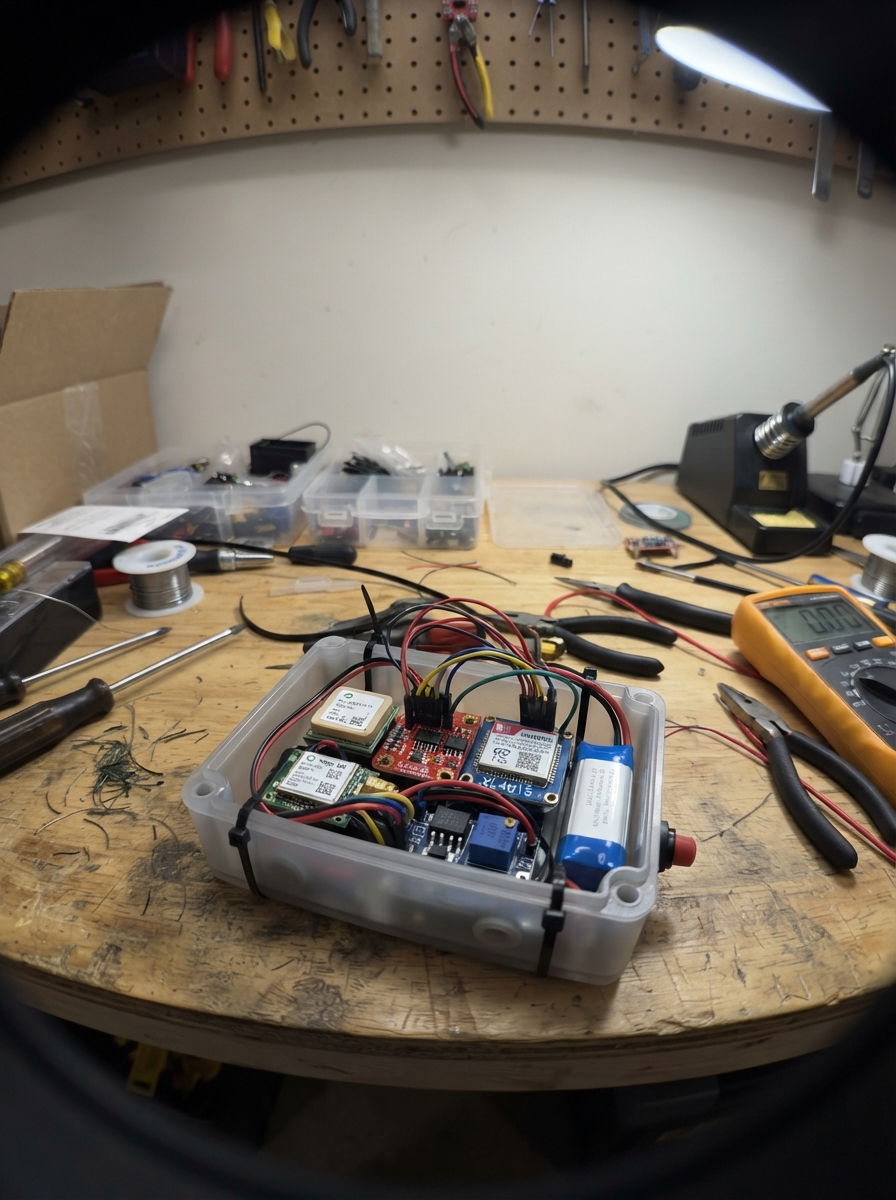
This project builds a wearable fall-detection system for cyclists that automatically sends an emergency SMS with GPS coordinates when a significant impact is detected. The ESP32 microcontroller monitors acceleration data from a 6-axis motion sensor, triggers an alert on hard impacts, and gives the rider 20 seconds to cancel before sending the message via GSM cellular network.
The guide provides a complete parts list, wiring diagram showing the dual buck converters and safety resistor network for the GSM module, step-by-step assembly instructions, and ready-to-customize firmware. Builders will learn to integrate GPS, motion sensing, and cellular communication while managing power delivery from a rechargeable battery pack.
Wiring diagram

Gather all the parts
Assemble it in 7 steps
1. Set the two converter voltages before connecting the electronics
Connect the protected battery pack to each XL4015 input: battery positive to each IN+ terminal and battery negative to each IN- terminal. Use a multimeter and adjust buck_5v_1 to exactly 5.0 V and buck_4v_1 to exactly 4.0 V before connecting the ESP32 or SIM800L.
- Mark the 5.0 V and 4.0 V modules with tape so they cannot be mixed up later.
- Do not connect either output to the electronics until it has been measured; more than 4.4 V can damage the SIM800L.
2. Connect the battery power
Connect buck_5v_1 OUT+ to the ESP32 VIN or 5V pin (board power), and buck_5v_1 OUT- to ESP32 GND (ground). Connect buck_4v_1 OUT+ to gsm_1 VCC (radio power) and buck_4v_1 OUT- to gsm_1 GND (ground). Every ground named GND must be joined together.
- Place gsm_capacitor_1 close to the SIM800L: its + leg goes to the 4.0 V VCC connection (power), and its - striped leg goes to GND (ground).
- Make sure the capacitor’s striped negative leg goes to GND; reversing it can make it heat up or burst.
- Fit the SIM card and GSM antenna before powering the SIM800L.
3. Wire the GPS receiver
Connect gps_1 VCC to ESP32 3V3 (power), gps_1 GND to ESP32 GND (ground), and gps_1 TX to ESP32 GPIO16 (location data). Leave the GPS RX and PPS pins unconnected.
- Put the GPS antenna where it faces open sky; it may take several minutes to find its first location after being moved a long distance.
4. Wire the motion sensor
Connect imu_1 VIN to ESP32 3V3 (power), imu_1 GND to ESP32 GND (ground), imu_1 SDA to ESP32 GPIO21 (data), and imu_1 SCL to ESP32 GPIO22 (clock). Leave the IMU INT pin unconnected.
- Do not swap the sensor's power wires; swapped power can damage the small sensor board.
5. Wire the GSM signal leads and their two-resistor safety link
Connect gsm_1 TX to ESP32 GPIO26 (GSM data). For the other direction, connect ESP32 GPIO27 to divider_top_1 P1, connect divider_top_1 P2 and divider_bottom_1 P1 together with gsm_1 RX (reduced-voltage data), then connect divider_bottom_1 P2 to GND (ground).
- The 1 kΩ resistor goes between GPIO27 and the three-way junction; the 5.6 kΩ resistor goes from that junction to GND. This reduces the ESP32's signal voltage for the SIM800L.
- Do not connect GPIO27 directly to SIM800L RX; the direct 3.3 V signal can stress the SIM800L input.
6. Add the cancel button
Connect one cancel_button_1 leg to ESP32 GPIO4 (signal) and the other leg to ESP32 GND (ground). The program normally holds this signal high, so pressing the button connects it safely to ground and cancels a pending alert.
- If your small tactile switch has four legs, use one leg from each opposite side rather than two legs on the same side.
7. Mount and test the tracker safely
Secure the ESP32, IMU, GPS, GSM module, and battery so the motion sensor moves with the bicycle frame. Turn it on outdoors, wait for the GPS to find a location, then test with the bicycle stationary by giving the mounted sensor a controlled sharp bump. Press the cancel button during the 20-second wait to confirm that no SMS is sent.
- Do not test by crashing or dropping the bicycle. Replace the placeholder phone number in the firmware before relying on the alert.
Review all connections
1. Connections between "battery_1" and "ESP32"
2. Connections between "buck_4v_1" and "ESP32"
3. Connections between "buck_5v_1" and "ESP32"
4. Connections between "gsm_capacitor_1" and "ESP32"
5. Connections between "gps_1" and "ESP32"
6. Connections between "imu_1" and "ESP32"
7. Connections between "gsm_1" and "ESP32"
8. Connections between "divider_top_1" and "ESP32"
9. Connections between "divider_bottom_1" and "ESP32"
10. Connections between "cancel_button_1" and "ESP32"
Deploy the firmware
#include <Arduino.h>
#include <Wire.h>
#include <TinyGPS++.h>


// Forward declarations
void sendAT(const char *command, uint32_t waitMs);
void sendEmergencySMS();
bool readAccelerationG(float &magnitudeG);
void setupMPU6050();

constexpr int GPS_RX_PIN = 16;
constexpr int GSM_RX_PIN = 26;
constexpr int GSM_TX_PIN = 27;
constexpr int CANCEL_BUTTON_PIN = 4;
constexpr int I2C_SDA_PIN = 21;
constexpr int I2C_SCL_PIN = 22;

constexpr char EMERGENCY_NUMBER[] = "+15551234567";  // Replace before use.
constexpr uint32_t GPS_BAUD = 9600;
constexpr uint32_t GSM_BAUD = 9600;
constexpr uint32_t CANCEL_WINDOW_MS = 20000;
constexpr float IMPACT_THRESHOLD_G = 2.7f;
constexpr uint32_t IMPACT_COOLDOWN_MS = 5000;

HardwareSerial gpsSerial(2);
HardwareSerial gsmSerial(1);
TinyGPSPlus gps;

bool alertPending = false;
uint32_t alertStartedAt = 0;
uint32_t lastImpactAt = 0;

void sendAT(const char *command, uint32_t waitMs) {
  gsmSerial.println(command);
  uint32_t start = millis();
  while (millis() - start < waitMs) {
    while (gsmSerial.available()) {
      Serial.write(gsmSerial.read());
    }
    delay(1);
  }
}

void sendEmergencySMS() {
  String message = "Cycle fall alert. Please check on me. ";
  if (gps.location.isValid() && gps.location.age() < 15000) {
    message += "GPS: https://maps.google.com/?q=";
    message += String(gps.location.lat(), 6);
    message += ",";
    message += String(gps.location.lng(), 6);
  } else {
    message += "GPS location is not fixed yet.";
  }

  Serial.println("Sending emergency SMS.");
  sendAT("AT", 500);
  sendAT("AT+CMGF=1", 500);
  gsmSerial.print("AT+CMGS=\"");
  gsmSerial.print(EMERGENCY_NUMBER);
  gsmSerial.println("\"");
  delay(500);
  gsmSerial.print(message);
  gsmSerial.write(26);  // Ctrl+Z sends the composed SMS.
  uint32_t start = millis();
  while (millis() - start < 10000) {
    while (gsmSerial.available()) {
      Serial.write(gsmSerial.read());
    }
    delay(1);
  }
}

bool readAccelerationG(float &magnitudeG) {
  Wire.beginTransmission(0x68);
  Wire.write(0x3B);
  if (Wire.endTransmission(false) != 0 || Wire.requestFrom(0x68, 6, true) != 6) {
    return false;
  }
  int16_t ax = (Wire.read() << 8) | Wire.read();
  int16_t ay = (Wire.read() << 8) | Wire.read();
  int16_t az = (Wire.read() << 8) | Wire.read();
  const float x = ax / 16384.0f;
  const float y = ay / 16384.0f;
  const float z = az / 16384.0f;
  magnitudeG = sqrtf(x * x + y * y + z * z);
  return true;
}

void setupMPU6050() {
  Wire.beginTransmission(0x68);
  Wire.write(0x6B);
  Wire.write(0x00);  // Wake the MPU6050.
  Wire.endTransmission();
  delay(100);
}

void setup() {
  Serial.begin(115200);
  pinMode(CANCEL_BUTTON_PIN, INPUT_PULLUP);
  Wire.begin(I2C_SDA_PIN, I2C_SCL_PIN);
  setupMPU6050();
  gpsSerial.begin(GPS_BAUD, SERIAL_8N1, GPS_RX_PIN, -1);
  gsmSerial.begin(GSM_BAUD, SERIAL_8N1, GSM_RX_PIN, GSM_TX_PIN);
  Serial.println("Cycle fall alert tracker ready.");
}

void loop() {
  while (gpsSerial.available()) {
    gps.encode(gpsSerial.read());
  }

  if (alertPending) {
    if (digitalRead(CANCEL_BUTTON_PIN) == LOW) {
      alertPending = false;
      Serial.println("Emergency alert cancelled.");
      delay(300);  // A quick tap counts only once.
    } else if (millis() - alertStartedAt >= CANCEL_WINDOW_MS) {
      alertPending = false;
      sendEmergencySMS();
    }
    delay(10);
    return;
  }

  float accelerationG = 0.0f;
  if (readAccelerationG(accelerationG) &&
      accelerationG >= IMPACT_THRESHOLD_G &&
      millis() - lastImpactAt >= IMPACT_COOLDOWN_MS) {
    lastImpactAt = millis();
    alertPending = true;
    alertStartedAt = millis();
    Serial.println("Possible fall detected. Press the cancel button within 20 seconds.");
  }
  delay(50);
}
Remix this project
Make it yours in one click
Open a full copy of this project in your own Schematik workspace — diagram, code, parts, and assembly steps included. Swap the sensor, add features, or redesign the whole thing with AI. The author's original stays untouched.