Community project
ESP32 Room Motion Alarm
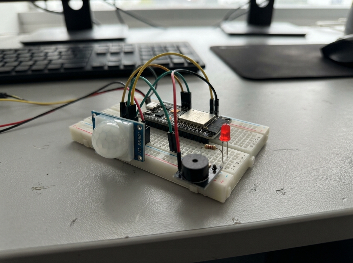
This ESP32 room motion alarm detects movement with a PIR sensor and triggers a 30-second alert using a buzzer and LED. The alarm automatically resets after motion stops, making it useful for room security, intruder detection, or occupancy monitoring in workshops and living spaces.
The guide includes a complete wiring diagram, parts list, and ready-to-flash firmware. Assembly takes just a few minutes: connect the motion sensor, buzzer, and LED to the ESP32 pins, then power it up. After a 60-second warmup period, the alarm is armed and ready to detect any movement.
Wiring diagram

Gather all the parts
Assemble it in 5 steps
1. Place the parts without power
Put the ESP32 board, motion sensor, buzzer module, red LED, and the three resistors on a breadboard or beside it. Leave the ESP32 unplugged while you make every wire connection.
- Keep the LED legs in different breadboard rows so they cannot touch.
- The 20 kΩ and 10 kΩ resistors can face either direction.
- Do not connect the ESP32 to USB until you have checked the power and ground wires; a misplaced power wire can damage a part.
2. Connect the motion sensor
Connect the HC-SR501 motion sensor VCC pin to the ESP32 5V/VIN pin (power), and connect its GND pin to an ESP32 GND pin (ground). Connect the sensor OUT pin to one end of the 20 kΩ resistor (motion signal). Connect the other end of that 20 kΩ resistor to GPIO27, and also connect that same GPIO27 row to one end of the 10 kΩ resistor (safe signal level). Connect the free end of the 10 kΩ resistor to GND (ground).
- GPIO27 is normally labelled 27 on the ESP32 board.
- The two resistors make the sensor signal safe for the ESP32's 3.3 V input.
- Do not connect the motion sensor OUT pin directly to GPIO27 in this design; the resistor pair is needed to keep the ESP32 input safe.
3. Connect the sounder
Connect the buzzer module SIGNAL or IN pin to GPIO25 (alarm signal). Connect its GND pin to an ESP32 GND pin (ground). If your buzzer module also has a VCC pin, connect that VCC pin to the ESP32 3V3 pin (power); this project expects a 3.3 V active buzzer module.
- An active buzzer makes a steady sound when its signal pin is turned on.
- All parts must share the ESP32 ground connection.
- Do not use a bare high-power buzzer on GPIO25; use the small 3.3 V active buzzer module specified for this project.
4. Connect the red warning light
Put the long LED leg into a free breadboard row and connect it to one end of the 220 Ω resistor. Connect the other end of that resistor to GPIO26 (light signal). Connect the LED's short leg, the flat-side leg, to GND (ground).
- The long LED leg is positive; the short leg next to the flat edge is negative.
- The 220 Ω resistor can go on either side of the LED, but it must stay in series with it.
- Never connect the LED directly between GPIO26 and ground without the 220 Ω resistor; too much current can damage the LED or the ESP32 pin.
5. Power and position the alarm
Recheck that every GND wire reaches an ESP32 GND pin, then plug the ESP32 into USB for power. Point the motion sensor toward the part of the room you want to watch and keep it still for its first minute while it settles.
- After the first 60 seconds, movement turns on the buzzer and red LED. The warning turns off 30 seconds after the last movement.
- Use the two small adjustment screws on the HC-SR501 only after basic testing if you want to change its range or how long its OUT signal stays high.
- Keep the sensor away from heating vents, direct sunlight, and moving curtains because they can cause unwanted motion alerts.
Review all connections
1. Connections between "pir_1" and "ESP32"
2. Connections between "pir_divider_bottom" and "ESP32"
3. Connections between "buzzer_1" and "ESP32"
4. Connections between "alarm_led" and "ESP32"
5. Connections between "led_resistor" and "ESP32"
6. Connections between "pir_divider_top" and "ESP32"
Deploy the firmware
#include <Arduino.h>
// Room security alert for ESP32 DevKit v1
// Motion starts a 30-second sound-and-light alert.


// Forward declarations
void setAlarmOutputs(bool on);

const int PIR_PIN = 27;
const int BUZZER_PIN = 25;
const int LED_PIN = 26;

const unsigned long ALARM_TIME_MS = 30000;
const unsigned long PIR_WARMUP_MS = 60000;

bool alarmActive = false;
unsigned long alarmStartedAt = 0;
unsigned long lastMotionAt = 0;

void setAlarmOutputs(bool on) {
  digitalWrite(LED_PIN, on ? HIGH : LOW);
  digitalWrite(BUZZER_PIN, on ? HIGH : LOW);
}

void setup() {
  pinMode(PIR_PIN, INPUT);
  pinMode(BUZZER_PIN, OUTPUT);
  pinMode(LED_PIN, OUTPUT);
  setAlarmOutputs(false);

  Serial.begin(115200);
  Serial.println("Room security alert starting");
  Serial.println("Waiting 60 seconds for the motion sensor to settle...");
  delay(PIR_WARMUP_MS);
  Serial.println("Alarm armed");
}

void loop() {
  const unsigned long now = millis();
  const bool motionDetected = digitalRead(PIR_PIN) == HIGH;

  if (motionDetected && !alarmActive) {
    alarmActive = true;
    alarmStartedAt = now;
    lastMotionAt = now;
    setAlarmOutputs(true);
    Serial.println("Motion detected: ALARM ON");
  }

  if (alarmActive && motionDetected) {
    lastMotionAt = now;
  }

  // Keep the warning on while movement continues, then turn it off
  // 30 seconds after the last detected movement.
  if (alarmActive && now - lastMotionAt >= ALARM_TIME_MS) {
    alarmActive = false;
    setAlarmOutputs(false);
    Serial.println("Area quiet: alarm reset and armed again");
  }

  delay(20);
}
Remix this project
Make it yours in one click
Open a full copy of this project in your own Schematik workspace — diagram, code, parts, and assembly steps included. Swap the sensor, add features, or redesign the whole thing with AI. The author's original stays untouched.
Related projects

Create A Complete Electrical Schematic Esp32 Sma
ESP32 · September 17, 2026Ayansh Agrawal
ESP32 Kare Ekran Projeleri
ESP32 · September 16, 2026Seref Ai
Component Qty --------------------------- ------
ESP32 · September 16, 2026Yathartha Chakrawal