Community project
ESP32 SIP Phone
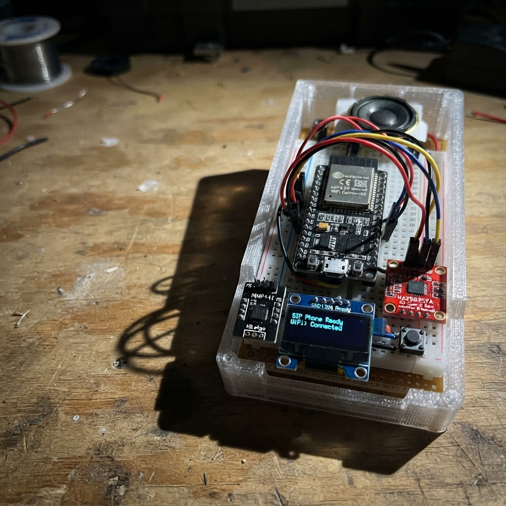
Build a working SIP phone using an ESP32 microcontroller, complete with audio input and output, a small display, and push buttons for call control. This project demonstrates real-time voice communication over WiFi using the Session Initiation Protocol, letting you make and receive calls to any SIP-compatible endpoint.
The guide provides a complete wiring diagram, parts list, and step-by-step assembly instructions for connecting the INMP441 microphone, MAX98357A amplifier, SSD1306 OLED display, and control buttons to the ESP32. Firmware is included with WiFi provisioning, SIP call handling, audio codec support, and a web interface for configuring your SIP server details.
Wiring diagram

Gather all the parts
Assemble it in 6 steps
1. Place the board and power rails
Place the ESP32-S3 board, OLED, microphone, amplifier, buttons, and speaker on a breadboard or in a case. Use the board's 3V3 pin as the positive rail and any GND pin as the ground rail; all modules must share this same ground.
- Use short wires for the microphone and amplifier clock wires so call audio is less likely to pick up noise.
- Do not power any of these signal pins from 5 V — the ESP32-S3 uses 3.3 V signals and 5 V can damage it.
2. Wire the OLED screen
Connect OLED VCC to 3V3 (power), OLED GND to GND (ground), OLED SDA to GPIO8 (data), and OLED SCL to GPIO9 (clock).
- The screen should show the phone status and, after Wi-Fi connects, its setup-page address.
- Make sure VCC and GND are not swapped — swapped power can damage the screen.
3. Wire the microphone
Connect INMP441 VDD to 3V3 (power), GND to GND (ground), SCK to GPIO14 (shared audio clock), WS to GPIO15 (shared left/right timing), SD to GPIO16 (microphone sound data), and L/R to GND (selects the left microphone channel).
- GPIO14 and GPIO15 each branch to the amplifier in the next step; they are shared timing wires, not separate pins.
- Do not connect the INMP441 SD wire to GPIO17; GPIO17 is the separate sound-output wire going to the amplifier.
4. Wire the amplifier and speaker
Connect MAX98357A VIN to 3V3 (power), GND to GND (ground), BCLK to the same GPIO14 wire used by INMP441 SCK (shared audio clock), LRC to the same GPIO15 wire used by INMP441 WS (shared timing), and DIN to GPIO17 (speaker sound data). Connect amplifier SPK+ to speaker POS (speaker signal) and amplifier SPK- to speaker NEG (speaker signal).
- Connect the speaker only to SPK+ and SPK-; these are a pair and neither speaker wire goes to GND.
- Never connect either SPK terminal to ground — that can damage the amplifier.
5. Wire the four buttons
For each push button, put one leg on GND (ground). Put the other leg of the place-call button on GPIO4 (signal), hang-up button on GPIO5 (signal), volume button on GPIO6 (signal), and mute button on GPIO7 (signal).
- If a four-leg breadboard button seems permanently pressed, rotate it 90 degrees; the two legs on each side are already joined inside the button.
- Do not connect a button signal leg to 3V3; the firmware already holds each signal high safely and the button makes it low when pressed.
6. Start and provision the phone
Inspect every 3V3 and GND wire one more time, then connect the ESP32-S3 to USB. After deployment, use a phone or computer to join the temporary Wi-Fi network named SIP-Phone-Setup with password phone-setup, open the setup page at 192.168.4.1, and save your Wi-Fi and direct SIP peer details. The OLED then shows the phone's address on your normal Wi-Fi network.
- The called SIP peer must accept an unregistered direct SIP INVITE and use G.711 μ-law (PCMU) audio.
- Do not use this as an emergency telephone: it has no registration, no dial plan, and no emergency-calling support.
Review all connections
1. Connections between "mic_1" and "ESP32"
2. Connections between "amp_1" and "ESP32"
3. Connections between "oled_1" and "ESP32"
4. Connections between "call_button" and "ESP32"
5. Connections between "hangup_button" and "ESP32"
6. Connections between "volume_button" and "ESP32"
7. Connections between "mute_button" and "ESP32"
Deploy the firmware
#include <Arduino.h>
#include <WiFi.h>
#include <WebServer.h>
#include <Preferences.h>
#include <Wire.h>
#include <Adafruit_GFX.h>
#include <Adafruit_SSD1306.h>
#include <driver/i2s.h>
struct Settings {
String sipHost, sipUser, destination;
uint16_t sipPort = 5060;
} cfg;
// Forward declarations
// Forward declarations
String headerValue(const String &message, const String &name);
void drawStatus();
String htmlEscape(const String &s);
void handleRoot();
void saveSettings();
void loadSettings();
void startNetwork();
void initAudio();
uint8_t linearToUlaw(int16_t pcm);
int16_t ulawToLinear(uint8_t u);
void sendSipInvite();
void processSip();
void sendSipAck();
void sendSipBye();
void sendSipCancel();
void hangup();
void processAudio();
void receiveAudio();
bool pressed(int pin);
// Put the Wi-Fi network used by this phone here before deploying.
constexpr char WIFI_SSID[] = "CGA2";
constexpr char WIFI_PASSWORD[] = "cganet12";
constexpr int CALL_BUTTON_PIN = 4;
constexpr int HANGUP_BUTTON_PIN = 5;
constexpr int VOLUME_BUTTON_PIN = 6;
constexpr int MUTE_BUTTON_PIN = 7;
constexpr int OLED_SDA_PIN = 8;
constexpr int OLED_SCL_PIN = 9;
constexpr int I2S_BCLK_PIN = 14;
constexpr int I2S_LRCLK_PIN = 15;
constexpr int I2S_MIC_DATA_PIN = 16;
constexpr int I2S_SPK_DATA_PIN = 17;
constexpr uint16_t SCREEN_WIDTH = 128;
constexpr uint16_t SCREEN_HEIGHT = 64;
constexpr uint16_t SIP_PORT = 5060;
constexpr uint16_t RTP_LOCAL_PORT = 40000;
constexpr uint16_t SAMPLE_RATE = 8000;
constexpr size_t FRAME_SAMPLES = 160; // 20 ms at 8 kHz
Adafruit_SSD1306 display(SCREEN_WIDTH, SCREEN_HEIGHT, &Wire, -1);
WebServer server(80);
Preferences prefs;
WiFiUDP sipUdp;
WiFiUDP rtpUdp;
bool inCall = false;
bool muted = false;
bool portalMode = false;
uint8_t volumeLevel = 4;
uint16_t rtpSequence = 1;
uint32_t rtpTimestamp = 0;
uint32_t rtpSsrc = 0x53495031;
uint32_t lastAudioMs = 0;
IPAddress rtpRemoteIp;
uint16_t rtpRemotePort = 0;
bool mediaNegotiated = false;
bool sipDialogEstablished = false;
uint32_t sipDialogCseq = 1;
String inviteBranch, inviteFromTag, inviteCallId, inviteToHeader, inviteRequestUri;
String statusLine = "Starting";
void drawStatus() {
display.clearDisplay();
display.setTextColor(SSD1306_WHITE);
display.setTextSize(1);
display.setCursor(0, 0);
display.println("ESP32-S3 SIP Phone");
display.drawLine(0, 10, 127, 10, SSD1306_WHITE);
display.setCursor(0, 15);
display.print("WiFi: ");
display.println(WiFi.status() == WL_CONNECTED ? WiFi.localIP().toString() : "not connected");
display.setCursor(0, 27);
display.print("SIP: ");
display.println(cfg.sipHost.length() ? cfg.sipHost : "not set");
display.setCursor(0, 39);
display.println(statusLine);
display.setCursor(0, 52);
display.print(inCall ? "CALL " : "IDLE ");
display.print(muted ? "MUTED " : "LIVE ");
display.print("VOL ");
display.print(volumeLevel);
display.display();
}
String htmlEscape(const String &s) {
String o = s;
o.replace("&", "&"); o.replace("\"", """); o.replace("<", "<"); o.replace(">", ">");
return o;
}
void handleRoot() {
String page = "<!doctype html><html><head><meta name='viewport' content='width=device-width'><title>SIP Phone Setup</title>"
"<style>body{font-family:system-ui;max-width:600px;margin:2rem auto;padding:0 1rem}input{width:100%;padding:.6rem;margin:.25rem 0 1rem;box-sizing:border-box}button{padding:.7rem 1rem}</style></head><body>"
"<h1>ESP32-S3 SIP Phone</h1><p>This phone joins the Wi-Fi network set in its firmware and does not register with a SIP service. Set the SIP server or direct SIP peer it should call.</p>"
"<form method='post' action='/save'>"
"<label>SIP server / peer address</label><input name='host' value='" + htmlEscape(cfg.sipHost) + "' placeholder='192.168.1.50'>"
"<label>SIP port</label><input name='port' type='number' value='" + String(cfg.sipPort) + "'>"
"<label>From name or extension</label><input name='user' value='" + htmlEscape(cfg.sipUser) + "'>"
"<label>Number / SIP user to call</label><input name='destination' value='" + htmlEscape(cfg.destination) + "'>"
"<button type='submit'>Save and restart Wi-Fi</button></form></body></html>";
server.send(200, "text/html", page);
}
void saveSettings() {
cfg.sipHost = server.arg("host");
cfg.sipPort = (uint16_t)server.arg("port").toInt(); if (!cfg.sipPort) cfg.sipPort = SIP_PORT;
cfg.sipUser = server.arg("user"); cfg.destination = server.arg("destination");
prefs.begin("sipphone", false);
prefs.putString("host", cfg.sipHost); prefs.putUShort("port", cfg.sipPort);
prefs.putString("user", cfg.sipUser); prefs.putString("dest", cfg.destination); prefs.end();
server.send(200, "text/html", "<h1>Saved</h1><p>The SIP settings were saved. Wi-Fi credentials are fixed in the firmware.</p>");
statusLine = "SIP settings saved";
drawStatus();
}
void loadSettings() {
// Open read/write on first boot so the Preferences namespace can be created.
if (!prefs.begin("sipphone", false)) {
Serial.println("Preferences unavailable");
return;
}
// Test for each saved item before reading it. On a new phone, absent values are normal.
cfg.sipHost = prefs.isKey("host") ? prefs.getString("host") : "";
cfg.sipPort = prefs.isKey("port") ? prefs.getUShort("port") : SIP_PORT;
cfg.sipUser = prefs.isKey("user") ? prefs.getString("user") : "phone";
cfg.destination = prefs.isKey("dest") ? prefs.getString("dest") : "";
prefs.end();
}
void startNetwork() {
WiFi.mode(WIFI_STA);
WiFi.begin(WIFI_SSID, WIFI_PASSWORD);
statusLine = "Joining WiFi";
Serial.println("Joining configured WiFi");
}
void initAudio() {
i2s_config_t icfg = {};
icfg.mode = (i2s_mode_t)(I2S_MODE_MASTER | I2S_MODE_TX | I2S_MODE_RX);
icfg.sample_rate = SAMPLE_RATE; icfg.bits_per_sample = I2S_BITS_PER_SAMPLE_32BIT;
icfg.channel_format = I2S_CHANNEL_FMT_RIGHT_LEFT; icfg.communication_format = I2S_COMM_FORMAT_STAND_I2S;
icfg.intr_alloc_flags = ESP_INTR_FLAG_LEVEL1; icfg.dma_buf_count = 8; icfg.dma_buf_len = FRAME_SAMPLES;
icfg.use_apll = false; icfg.tx_desc_auto_clear = true; icfg.fixed_mclk = 0;
i2s_driver_install(I2S_NUM_0, &icfg, 0, nullptr);
i2s_pin_config_t pins = {};
pins.bck_io_num = I2S_BCLK_PIN; pins.ws_io_num = I2S_LRCLK_PIN; pins.data_out_num = I2S_SPK_DATA_PIN; pins.data_in_num = I2S_MIC_DATA_PIN;
i2s_set_pin(I2S_NUM_0, &pins); i2s_zero_dma_buffer(I2S_NUM_0);
}
// ITU-T G.711 μ-law encoder for a signed 16-bit PCM sample.
// The segment number must increase with signal magnitude; reversing that
// relationship produces severe speech distortion even though RTP is valid.
uint8_t linearToUlaw(int16_t sample) {
constexpr int BIAS = 0x84;
constexpr int CLIP = 32635;
int pcm = sample;
uint8_t mask;
if (pcm < 0) {
pcm = -pcm;
mask = 0x7F;
} else {
mask = 0xFF;
}
if (pcm > CLIP) pcm = CLIP;
pcm += BIAS;
// Segment 0 covers 0x00ff, segment 1 covers 0x01ff, and so on.
int seg = 0;
int magnitude = pcm >> 7;
while (magnitude > 1 && seg < 7) {
magnitude >>= 1;
++seg;
}
uint8_t ulaw = (uint8_t)((seg << 4) | ((pcm >> (seg + 3)) & 0x0F));
return ulaw ^ mask;
}
int16_t ulawToLinear(uint8_t u) {
u = ~u; int t = ((u & 0x0F) << 3) + 0x84; t <<= (u & 0x70) >> 4;
return (u & 0x80) ? (0x84 - t) : (t - 0x84);
}
String headerValue(const String &message, const String &name) {
int start = message.indexOf(name + ":");
if (start < 0) return "";
start += name.length() + 1;
while (start < message.length() && message[start] == ' ') start++;
int end = message.indexOf("\r\n", start);
return message.substring(start, end < 0 ? message.length() : end);
}
void sendSipInvite() {
IPAddress peer;
if (!peer.fromString(cfg.sipHost.c_str())) { statusLine = "SIP host must be an IP"; drawStatus(); return; }
inviteBranch = "z9hG4bK" + String((uint32_t)esp_random(), HEX);
inviteFromTag = String((uint32_t)esp_random(), HEX);
inviteCallId = String((uint32_t)esp_random(), HEX) + "@esp32";
inviteToHeader = "<sip:" + cfg.destination + "@" + cfg.sipHost + ">";
inviteRequestUri = "sip:" + cfg.destination + "@" + cfg.sipHost + ":" + String(cfg.sipPort);
mediaNegotiated = false; rtpRemotePort = 0;
sipDialogEstablished = false; sipDialogCseq = 1;
String from = cfg.sipUser.length() ? cfg.sipUser : "phone";
String sdp = "v=0\r\no=- 1 1 IN IP4 " + WiFi.localIP().toString() + "\r\ns=ESP32 SIP Phone\r\nc=IN IP4 " + WiFi.localIP().toString() + "\r\nt=0 0\r\nm=audio " + String(RTP_LOCAL_PORT) + " RTP/AVP 0\r\na=rtpmap:0 PCMU/8000\r\na=sendrecv\r\n";
String invite = "INVITE sip:" + cfg.destination + "@" + cfg.sipHost + ":" + String(cfg.sipPort) + " SIP/2.0\r\n"
"Via: SIP/2.0/UDP " + WiFi.localIP().toString() + ":" + String(SIP_PORT) + ";branch=" + inviteBranch + "\r\n"
"From: <sip:" + from + "@" + WiFi.localIP().toString() + ">;tag=" + inviteFromTag + "\r\n"
"To: " + inviteToHeader + "\r\n"
"Call-ID: " + inviteCallId + "\r\nCSeq: 1 INVITE\r\nContact: <sip:" + from + "@" + WiFi.localIP().toString() + ":" + String(SIP_PORT) + ">\r\n"
"Content-Type: application/sdp\r\nContent-Length: " + String(sdp.length()) + "\r\n\r\n" + sdp;
sipUdp.beginPacket(peer, cfg.sipPort); sipUdp.print(invite); sipUdp.endPacket();
Serial.println("--- SIP INVITE sent ---");
Serial.printf("SIP peer: %s:%u, destination: %s, local RTP port: %u\n", cfg.sipHost.c_str(), cfg.sipPort, cfg.destination.c_str(), RTP_LOCAL_PORT);
Serial.println(sdp);
inCall = true; statusLine = "Dialing " + cfg.destination; drawStatus();
}
void sendSipAck() {
IPAddress peer;
if (!peer.fromString(cfg.sipHost.c_str())) {
Serial.println("ACK not sent: SIP server address is invalid.");
return;
}
String from = cfg.sipUser.length() ? cfg.sipUser : "phone";
String requestUri = inviteRequestUri.length() ? inviteRequestUri : "sip:" + cfg.destination + "@" + cfg.sipHost + ":" + String(cfg.sipPort);
String ack = "ACK " + requestUri + " SIP/2.0\r\n"
"Via: SIP/2.0/UDP " + WiFi.localIP().toString() + ":" + String(SIP_PORT) + ";branch=z9hG4bK" + String((uint32_t)esp_random(), HEX) + "\r\n"
"From: <sip:" + from + "@" + WiFi.localIP().toString() + ">;tag=" + inviteFromTag + "\r\n"
"To: " + inviteToHeader + "\r\nCall-ID: " + inviteCallId + "\r\nCSeq: 1 ACK\r\nContent-Length: 0\r\n\r\n";
sipUdp.beginPacket(peer, cfg.sipPort);
sipUdp.print(ack);
sipUdp.endPacket();
Serial.println("--- SIP ACK sent for 200 OK ---");
Serial.printf("ACK transport destination: %s:%u, request URI: %s\n", peer.toString().c_str(), cfg.sipPort, requestUri.c_str());
Serial.println(ack);
}
void processSip() {
int len = sipUdp.parsePacket();
if (len <= 0) return;
char buffer[1501];
int read = sipUdp.read((uint8_t *)buffer, min(len, 1500));
if (read <= 0) return;
buffer[read] = '\0';
String response(buffer);
Serial.println("--- SIP packet received ---");
Serial.printf("Bytes: %d, source: %s:%u\n", read, sipUdp.remoteIP().toString().c_str(), sipUdp.remotePort());
Serial.println(response);
if (!response.startsWith("SIP/2.0 200")) {
Serial.println("SIP packet ignored: it is not a 200 OK.");
return;
}
if (!inCall || mediaNegotiated) {
Serial.printf("200 OK ignored: inCall=%d, mediaNegotiated=%d\n", inCall, mediaNegotiated);
return;
}
int body = response.indexOf("\r\n\r\n");
String sdp = body >= 0 ? response.substring(body + 4) : "";
Serial.println("--- SDP received in 200 OK ---");
Serial.println(sdp.length() ? sdp : "<no SDP body>");
int media = sdp.indexOf("m=audio ");
int connection = sdp.indexOf("c=IN IP4 ");
Serial.printf("SDP indexes: body=%d, m=audio=%d, c=IN IP4=%d\n", body, media, connection);
if (media < 0 || connection < 0) { Serial.println("SDP error: missing m=audio or IPv4 c= line."); statusLine = "200 OK has no audio SDP"; drawStatus(); return; }
int portStart = media + 8, portEnd = sdp.indexOf(' ', portStart);
// "c=IN IP4 " is exactly 9 characters. Start at the first digit of the IPv4 address.
int ipStart = connection + 9, ipEnd = sdp.indexOf('\r', ipStart);
String portText = sdp.substring(portStart, portEnd);
String ipText = sdp.substring(ipStart, ipEnd < 0 ? sdp.length() : ipEnd);
uint16_t port = (uint16_t)portText.toInt();
IPAddress address;
Serial.printf("SDP extracted: address='%s', port='%s' -> %s:%u\n", ipText.c_str(), portText.c_str(), ipText.c_str(), port);
if (!port || !address.fromString(ipText)) { Serial.println("SDP error: extracted address or port is invalid."); statusLine = "Invalid audio SDP"; drawStatus(); return; }
String to = headerValue(response, "To");
if (to.length()) inviteToHeader = to;
String contact = headerValue(response, "Contact");
if (contact.length()) {
int uriStart = contact.indexOf('<');
int uriEnd = contact.indexOf('>', uriStart + 1);
if (uriStart >= 0 && uriEnd > uriStart + 1) {
inviteRequestUri = contact.substring(uriStart + 1, uriEnd);
Serial.printf("200 OK Contact selected for ACK request URI: %s\n", inviteRequestUri.c_str());
} else {
Serial.println("200 OK Contact was present but did not contain a bracketed SIP URI; using original request URI.");
}
} else {
Serial.println("200 OK has no Contact header; using original request URI for ACK.");
}
rtpRemoteIp = address; rtpRemotePort = port; mediaNegotiated = true;
Serial.printf("RTP destination accepted: %s:%u, codec=PCMU/8000, payload type=0\n", rtpRemoteIp.toString().c_str(), rtpRemotePort);
sendSipAck();
sipDialogEstablished = true;
statusLine = "In call"; Serial.printf("RTP peer: %s:%u\n", rtpRemoteIp.toString().c_str(), rtpRemotePort); drawStatus();
}
void sendSipBye() {
IPAddress peer;
if (!peer.fromString(cfg.sipHost.c_str())) {
Serial.println("BYE not sent: SIP server address is invalid.");
return;
}
String from = cfg.sipUser.length() ? cfg.sipUser : "phone";
uint32_t byeCseq = ++sipDialogCseq;
String requestUri = inviteRequestUri.length() ? inviteRequestUri : "sip:" + cfg.destination + "@" + cfg.sipHost + ":" + String(cfg.sipPort);
String bye = "BYE " + requestUri + " SIP/2.0\r\n"
"Via: SIP/2.0/UDP " + WiFi.localIP().toString() + ":" + String(SIP_PORT) + ";branch=z9hG4bK" + String((uint32_t)esp_random(), HEX) + "\r\n"
"From: <sip:" + from + "@" + WiFi.localIP().toString() + ">;tag=" + inviteFromTag + "\r\n"
"To: " + inviteToHeader + "\r\n"
"Call-ID: " + inviteCallId + "\r\n"
"CSeq: " + String(byeCseq) + " BYE\r\n"
"Content-Length: 0\r\n\r\n";
sipUdp.beginPacket(peer, cfg.sipPort);
sipUdp.print(bye);
sipUdp.endPacket();
Serial.println("--- SIP BYE sent ---");
Serial.printf("BYE transport destination: %s:%u, request URI: %s, CSeq: %lu\n", peer.toString().c_str(), cfg.sipPort, requestUri.c_str(), (unsigned long)byeCseq);
Serial.println(bye);
}
void sendSipCancel() {
IPAddress peer;
if (!peer.fromString(cfg.sipHost.c_str())) return;
String from = cfg.sipUser.length() ? cfg.sipUser : "phone";
String cancel = "CANCEL " + inviteRequestUri + " SIP/2.0\r\n"
"Via: SIP/2.0/UDP " + WiFi.localIP().toString() + ":" + String(SIP_PORT) + ";branch=" + inviteBranch + "\r\n"
"From: <sip:" + from + "@" + WiFi.localIP().toString() + ">;tag=" + inviteFromTag + "\r\n"
"To: " + inviteToHeader + "\r\n"
"Call-ID: " + inviteCallId + "\r\nCSeq: 1 CANCEL\r\nContent-Length: 0\r\n\r\n";
sipUdp.beginPacket(peer, cfg.sipPort); sipUdp.print(cancel); sipUdp.endPacket();
Serial.println("--- SIP CANCEL sent while call was ringing ---");
Serial.println(cancel);
}
void hangup() {
if (sipDialogEstablished) sendSipBye();
else sendSipCancel();
inCall = false; mediaNegotiated = false; sipDialogEstablished = false; rtpRemotePort = 0;
i2s_zero_dma_buffer(I2S_NUM_0); statusLine = "Call ended"; drawStatus();
}
void processAudio() {
if (!inCall || millis() - lastAudioMs < 20) return;
lastAudioMs = millis();
// I2S_NUM_0 is configured for right/left 32-bit slots. The INMP441 L/R pin
// is tied to GND, so its 24-bit sample is in each LEFT slot. Read 160 stereo
// frames (320 words), not 160 individual slots, to make one 20 ms PCMU packet.
int32_t micSlots[FRAME_SAMPLES * 2];
size_t got = 0;
i2s_read(I2S_NUM_0, micSlots, sizeof(micSlots), &got, portMAX_DELAY);
if (got != sizeof(micSlots)) return;
uint8_t packet[12 + FRAME_SAMPLES];
packet[0] = 0x80; packet[1] = 0x00;
packet[2] = rtpSequence >> 8; packet[3] = rtpSequence++;
packet[4] = rtpTimestamp >> 24; packet[5] = rtpTimestamp >> 16;
packet[6] = rtpTimestamp >> 8; packet[7] = rtpTimestamp;
packet[8] = rtpSsrc >> 24; packet[9] = rtpSsrc >> 16;
packet[10] = rtpSsrc >> 8; packet[11] = rtpSsrc;
int peak = 0;
for (size_t i = 0; i < FRAME_SAMPLES; i++) {
// INMP441 is 24-bit, left-aligned in the 32-bit I2S word. Retaining its
// upper 16 bits gives the signed PCM amplitude G.711 expects.
int16_t pcm = (int16_t)(micSlots[i * 2] >> 16);
int magnitude = pcm < 0 ? -(int)pcm : (int)pcm;
if (magnitude > peak) peak = magnitude;
packet[12 + i] = muted ? 0xFF : linearToUlaw(pcm);
}
if (mediaNegotiated && rtpRemotePort) {
rtpUdp.beginPacket(rtpRemoteIp, rtpRemotePort);
rtpUdp.write(packet, sizeof(packet));
rtpUdp.endPacket();
}
static uint32_t lastMicReport = 0;
if (millis() - lastMicReport >= 1000) {
lastMicReport = millis();
Serial.printf("RTP TX: 50 PCMU packets/s, INMP441 left-channel peak=%d, muted=%d\n", peak, muted);
}
rtpTimestamp += FRAME_SAMPLES;
}
void receiveAudio() {
int len = rtpUdp.parsePacket(); if (len < 13) return;
uint8_t packet[300]; int n = rtpUdp.read(packet, sizeof(packet)); if (n <= 12) return;
int32_t out[FRAME_SAMPLES * 2]; size_t count = min((size_t)(n - 12), FRAME_SAMPLES);
for (size_t i = 0; i < count; i++) { int32_t s = ((int32_t)ulawToLinear(packet[12 + i]) * volumeLevel) << 16; out[i * 2] = s; out[i * 2 + 1] = s; }
size_t written; i2s_write(I2S_NUM_0, out, count * 2 * sizeof(int32_t), &written, 0);
}
bool pressed(int pin) { static uint32_t last[4] = {}; int index = pin - 4; if (digitalRead(pin) == LOW && millis() - last[index] > 250) { last[index] = millis(); return true; } return false; }
void setup() {
Serial.begin(115200); pinMode(CALL_BUTTON_PIN, INPUT_PULLUP); pinMode(HANGUP_BUTTON_PIN, INPUT_PULLUP); pinMode(VOLUME_BUTTON_PIN, INPUT_PULLUP); pinMode(MUTE_BUTTON_PIN, INPUT_PULLUP);
Wire.begin(OLED_SDA_PIN, OLED_SCL_PIN); display.begin(SSD1306_SWITCHCAPVCC, 0x3C); loadSettings(); initAudio(); startNetwork();
server.on("/", HTTP_GET, handleRoot); server.on("/save", HTTP_POST, saveSettings); server.begin(); sipUdp.begin(SIP_PORT); rtpUdp.begin(RTP_LOCAL_PORT); drawStatus();
}
void loop() {
server.handleClient();
processSip();
if (!portalMode && WiFi.status() == WL_CONNECTED && statusLine == "Joining WiFi") {
statusLine = "Ready: open OLED IP";
Serial.print("WiFi connected. SIP setup: http://");
Serial.println(WiFi.localIP());
drawStatus();
}
if (pressed(CALL_BUTTON_PIN) && !inCall) { if (WiFi.status() != WL_CONNECTED || !cfg.sipHost.length() || !cfg.destination.length()) { statusLine = "Check WiFi and SIP settings"; drawStatus(); } else sendSipInvite(); }
if (pressed(HANGUP_BUTTON_PIN) && inCall) hangup();
if (pressed(VOLUME_BUTTON_PIN)) { volumeLevel = volumeLevel == 8 ? 1 : volumeLevel + 1; statusLine = "Volume " + String(volumeLevel); drawStatus(); }
if (pressed(MUTE_BUTTON_PIN)) { muted = !muted; statusLine = muted ? "Microphone muted" : "Microphone live"; drawStatus(); }
processAudio(); receiveAudio();
}Remix this project
Make it yours in one click
Open a full copy of this project in your own Schematik workspace — diagram, code, parts, and assembly steps included. Swap the sensor, add features, or redesign the whole thing with AI. The author's original stays untouched.
Related projects

Create A Complete Electrical Schematic Esp32 Sma
ESP32 · September 17, 2026Ayansh Agrawal
ESP32 Kare Ekran Projeleri
ESP32 · September 16, 2026Seref Ai
Component Qty --------------------------- ------
ESP32 · September 16, 2026Yathartha Chakrawal