Community project
ESP32 Solenoid Door Lock
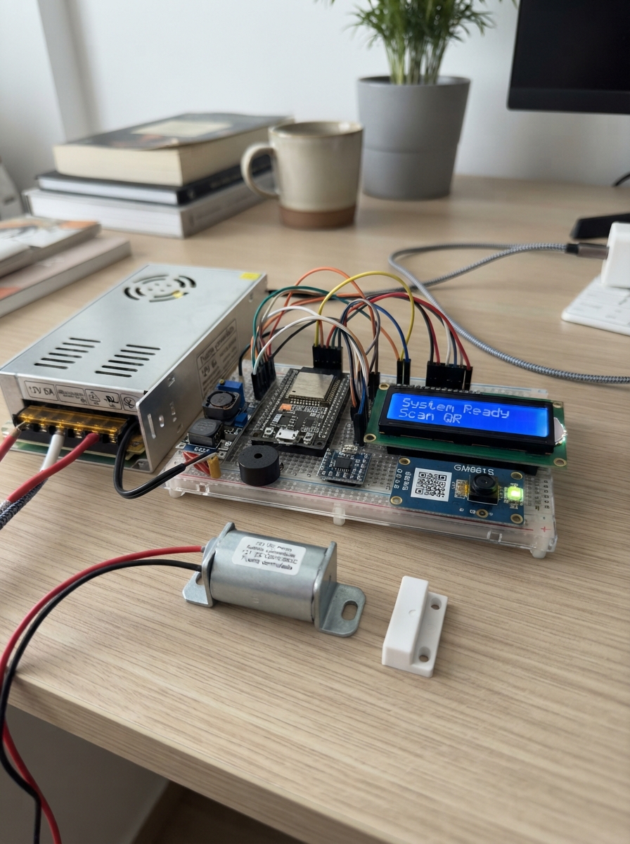
This project builds a networked four-door solenoid lock system controlled by an ESP32 microcontroller. The system reads QR codes for access, displays status on an LCD screen, and manages four independent 12V solenoid locks through relays with magnetic door sensors for feedback. A web interface allows remote monitoring and control over WiFi.
The guide provides a complete wiring diagram connecting the 12V power supply, buck converter, relay module, I2C expander, LCD display, QR reader, door sensors, and solenoid locks. You'll get a full parts list, step-by-step assembly instructions for integrating all components, and Arduino firmware that handles QR authentication, door state tracking, and web server functionality.
Wiring diagram

Gather all the parts
Assemble it in 9 steps
1. Instala la fuente de 12 V y el reductor
Usa psu_12v_1a de 12 V y 5 A. Con la fuente desconectada de la pared, conecta +12V a IN+ de xl4015_1 y a COM1, COM2, COM3 y COM4 de relay_4ch_5v_1 (energía para las cuatro cerraduras). Conecta 0V a IN- de xl4015_1 y al terminal 0V de cada cerradura (retorno).
- Usa cable más grueso para los trayectos de 12 V de las cerraduras.
- Los terminales de red eléctrica de la fuente deben quedar dentro de una caja cerrada; tocarlos puede causar una descarga eléctrica grave.
- No conectes la fuente a la pared mientras instalas los cables.
2. Ajusta la salida a 5 voltios
Con la fuente encendida y sin conectar todavía el ESP32, mide entre OUT+ y OUT- de xl4015_1. Gira el pequeño tornillo hasta que el multímetro marque exactamente 5,0 V; después desconecta la fuente.
- Mide dos veces: unas vueltas pequeñas del tornillo cambian el voltaje.
- No conectes el ESP32, la LCD ni el relé mientras la salida no sea 5,0 V; un voltaje mayor puede dañarlos.
3. Alimenta el relé y la pantalla
Conecta OUT+ de xl4015_1 a VIN o 5V del ESP32, VCC de relay_4ch_5v_1, VCC de lcd1602_1 y HV de i2c_level_shifter_1 (alimentación). Conecta OUT- a GND de todos ellos y a GND del ESP32 (tierra compartida).
- Nunca conectes los 12 V directamente al pin VIN o 5V del ESP32.
4. Conecta las cuatro cerraduras al relé único
Conecta NO1 de relay_4ch_5v_1 al +12V de solenoid_lock_1, NO2 al +12V de solenoid_lock_2, NO3 al +12V de solenoid_lock_3 y NO4 al +12V de solenoid_lock_4 (energía de apertura). El 0V de cada cerradura vuelve al 0V de la fuente (retorno).
- Los cuatro bornes COM ya reciben el +12 V desde la fuente.
- No uses los bornes NC: podrían dejar una cerradura alimentada de forma continua y hacer que se caliente.
5. Conecta las órdenes directamente al relé
Conecta GPIO25 a IN1 de relay_4ch_5v_1 (orden de puerta 1), GPIO32 a IN2 (orden de puerta 2), GPIO33 a IN3 (orden de puerta 3) y GPIO4 a IN4 (orden de puerta 4). Conecta SIGNAL de buzzer_1 a GPIO26 y GND de buzzer_1 a GND (sonido).
- El 74HCT125 fue eliminado por tu decisión. Si este relé de 5 V devuelve 5 V por IN1–IN4, puede dañar los pines de 3,3 V del ESP32. Desconecta la alimentación inmediatamente si el ESP32 se reinicia, se calienta o las órdenes son inestables.
6. Monta los sensores de las puertas
Fija cada sensor al marco y su imán a la puerta para que queden enfrentados al cerrar. Conecta CABLE 1 de magnetic_nc_1 a GPIO27 y CABLE 2 a GND (señal y tierra). Alimenta mcp23017_1: VCC a 3V3 y GND a GND. Conecta CABLE 1 de magnetic_nc_2 a GPA0, de magnetic_nc_3 a GPA1 y de magnetic_nc_4 a GPA2; conecta el otro cable de cada sensor a GND (señal y tierra).
- C significa cerrada; A significa abierta o cable desconectado.
- No dejes los cables donde el pestillo pueda aplastarlos; un cable roto se verá como una puerta abierta.
7. Conecta la pantalla y el expansor
Conecta GPIO21 a LV1 y GPIO22 a LV2 de i2c_level_shifter_1 (datos y reloj de 3,3 V). Conecta HV1 a SDA y HV2 a SCL de lcd1602_1 (datos y reloj de 5 V). Conecta SDA y SCL de mcp23017_1 a LV1 y LV2 del mismo conversor. Conecta LV de i2c_level_shifter_1 a 3V3 (referencia de señal).
- No conectes los cables SDA o SCL de la pantalla de 5 V directamente al ESP32; pueden dañar sus pines de 3,3 V.
8. Conecta el lector QR
Conecta VCC de gm861s_1 a 3V3 y GND a GND (alimentación). Conecta TXD de gm861s_1 a GPIO16 y RXD de gm861s_1 a GPIO17 (datos).
- Los textos PUERTA1, PUERTA2, PUERTA3 y PUERTA4 abren la puerta correspondiente durante tres segundos.
- No conectes VCC del GM861S a los 5 V del XL4015; este lector usa 3,3 V.
9. Enciende y prueba cada puerta
Revisa que no haya hilos sueltos. Conecta el ESP32 por USB, enciende la fuente de 12 V y usa Schematik para desplegar. Conecta el teléfono a Cerraduras-ESP32 con contraseña Abrir123, abre 192.168.4.1 y prueba una puerta por vez o escanea un QR autorizado.
- Dos pitidos cortos indican que el ESP32 arrancó.
- Durante la primera prueba, mantén los dedos lejos de los pestillos: una cerradura puede moverse con fuerza al recibir energía.
Review all connections
1. Connections between "psu_12v_1a" and "ESP32"
2. Connections between "xl4015_1" and "ESP32"
3. Connections between "relay_4ch_5v_1" and "ESP32"
4. Connections between "buzzer_1" and "ESP32"
5. Connections between "magnetic_nc_1" and "ESP32"
6. Connections between "gm861s_1" and "ESP32"
7. Connections between "i2c_level_shifter_1" and "ESP32"
8. Connections between "mcp23017_1" and "ESP32"
9. Connections between "magnetic_nc_2" and "ESP32"
10. Connections between "magnetic_nc_3" and "ESP32"
11. Connections between "magnetic_nc_4" and "ESP32"
Deploy the firmware
#include <Arduino.h>
#include <WiFi.h>
#include <WebServer.h>
#include <Wire.h>
#include <LiquidCrystal_I2C.h>
#include <Adafruit_MCP23X17.h>

constexpr int RELAY_1_PIN = 25;
constexpr int RELAY_2_PIN = 32;
constexpr int RELAY_3_PIN = 33;
constexpr int RELAY_4_PIN = 4;
constexpr int BUZZER_PIN = 26;
constexpr int DOOR_1_PIN = 27;
constexpr int QR_RX_PIN = 16;
constexpr int QR_TX_PIN = 17;
constexpr int I2C_SDA_PIN = 21;
constexpr int I2C_SCL_PIN = 22;
constexpr uint8_t MCP_DOOR_2_PIN = 0;
constexpr uint8_t MCP_DOOR_3_PIN = 1;
constexpr uint8_t MCP_DOOR_4_PIN = 2;
constexpr unsigned long UNLOCK_TIME_MS = 3000;

const char *AP_SSID = "Cerraduras-ESP32";
const char *AP_PASSWORD = "Abrir123";
const int relayPins[4] = {RELAY_1_PIN, RELAY_2_PIN, RELAY_3_PIN, RELAY_4_PIN};

WebServer server(80);
LiquidCrystal_I2C lcd(0x27, 16, 2);
Adafruit_MCP23X17 mcp;
HardwareSerial qrSerial(2);
int unlockedDoor = -1;
unsigned long unlockStartedAt = 0;
String lastMessage = "Listo";
String qrBuffer;
String lastLcd1, lastLcd2;

String fit16(String s) { while (s.length() < 16) s += ' '; return s.substring(0, 16); }
void beep(unsigned int ms) { tone(BUZZER_PIN, 2400, ms); }
void setRelay(uint8_t door, bool on) { digitalWrite(relayPins[door], on ? LOW : HIGH); }
bool doorClosed(uint8_t door) {
  if (door == 0) return digitalRead(DOOR_1_PIN) == LOW;
  const uint8_t mcpPins[3] = {MCP_DOOR_2_PIN, MCP_DOOR_3_PIN, MCP_DOOR_4_PIN};
  return mcp.digitalRead(mcpPins[door - 1]) == LOW;
}

void updateLcd(bool force = false) {
  String l1 = "P1:" + String(doorClosed(0) ? "C" : "A") + " P2:" + String(doorClosed(1) ? "C" : "A") + " P3:" + String(doorClosed(2) ? "C" : "A");
  String l2 = "P4:" + String(doorClosed(3) ? "C " : "A ") + lastMessage;
  l1 = fit16(l1); l2 = fit16(l2);
  if (force || l1 != lastLcd1) { lcd.setCursor(0, 0); lcd.print(l1); lastLcd1 = l1; }
  if (force || l2 != lastLcd2) { lcd.setCursor(0, 1); lcd.print(l2); lastLcd2 = l2; }
}

void openDoor(uint8_t door, const String &source) {
  if (unlockedDoor >= 0) setRelay(unlockedDoor, false);
  setRelay(door, true); unlockedDoor = door; unlockStartedAt = millis();
  lastMessage = "Abre P" + String(door + 1); updateLcd(); beep(120);
  Serial.println("Puerta " + String(door + 1) + " abierta por " + source);
}

String page() {
  String html = "<!doctype html><html lang='es'><meta name='viewport' content='width=device-width,initial-scale=1'><style>body{font-family:Arial;text-align:center;background:#f4f6f8;color:#17212b}button{font-size:19px;padding:13px;margin:6px;border:0;border-radius:9px;background:#087f23;color:white}.a{color:#b00020}.c{color:#087f23}</style><h1>Control de cerraduras</h1><p>QR autorizados: PUERTA1, PUERTA2, PUERTA3 y PUERTA4.</p>";
  for (uint8_t d = 0; d < 4; d++) {
    bool closed = doorClosed(d);
    html += "<p>Puerta " + String(d + 1) + ": <b class='" + String(closed ? "c" : "a") + "'>" + String(closed ? "CERRADA" : "ABIERTA O CABLE DESCONECTADO") + "</b><br><form action='/open?door=" + String(d + 1) + "' method='post'><button>Abrir puerta " + String(d + 1) + "</button></form></p>";
  }
  return html + "<p>Red Wi-Fi: <b>Cerraduras-ESP32</b></p></html>";
}

void handleHome() { server.send(200, "text/html; charset=utf-8", page()); }
void handleOpen() {
  int door = server.arg("door").toInt();
  if (door < 1 || door > 4) { server.send(400, "text/plain", "Puerta no valida"); return; }
  openDoor(door - 1, "pagina web"); server.sendHeader("Location", "/"); server.send(303);
}
void processQr(String code) {
  code.trim(); code.toUpperCase();
  for (uint8_t d = 0; d < 4; d++) if (code == "PUERTA" + String(d + 1)) { openDoor(d, "codigo QR"); return; }
  lastMessage = "QR no valido"; updateLcd(); beep(500);
}
void pollQr() {
  while (qrSerial.available()) {
    char c = static_cast<char>(qrSerial.read());
    if (c == '\r' || c == '\n') { if (qrBuffer.length()) { processQr(qrBuffer); qrBuffer = ""; } }
    else if (qrBuffer.length() < 64) qrBuffer += c;
  }
}

void setup() {
  Serial.begin(115200);
  for (uint8_t d = 0; d < 4; d++) { pinMode(relayPins[d], OUTPUT); setRelay(d, false); }
  pinMode(BUZZER_PIN, OUTPUT); pinMode(DOOR_1_PIN, INPUT_PULLUP); noTone(BUZZER_PIN);
  Wire.begin(I2C_SDA_PIN, I2C_SCL_PIN);
  lcd.init(); lcd.backlight();
  if (mcp.begin_I2C(0x20, &Wire)) {
    mcp.pinMode(MCP_DOOR_2_PIN, INPUT_PULLUP);
    mcp.pinMode(MCP_DOOR_3_PIN, INPUT_PULLUP);
    mcp.pinMode(MCP_DOOR_4_PIN, INPUT_PULLUP);
  } else lastMessage = "Error MCP23017";
  updateLcd(true);
  qrSerial.begin(9600, SERIAL_8N1, QR_RX_PIN, QR_TX_PIN);
  WiFi.mode(WIFI_AP); WiFi.softAP(AP_SSID, AP_PASSWORD);
  server.on("/", HTTP_GET, handleHome); server.on("/open", HTTP_POST, handleOpen); server.begin();
  beep(80); delay(140); beep(80);
}

void loop() {
  server.handleClient(); pollQr();
  if (unlockedDoor >= 0 && millis() - unlockStartedAt >= UNLOCK_TIME_MS) {
    setRelay(unlockedDoor, false); unlockedDoor = -1; lastMessage = "Cerrada"; updateLcd(); beep(180);
  }
  static unsigned long lastDisplayPoll = 0;
  if (millis() - lastDisplayPoll >= 250) { lastDisplayPoll = millis(); updateLcd(); }
}
Remix this project
Make it yours in one click
Open a full copy of this project in your own Schematik workspace — diagram, code, parts, and assembly steps included. Swap the sensor, add features, or redesign the whole thing with AI. The author's original stays untouched.