Community project
ESP32 Telegram Motion Alarm
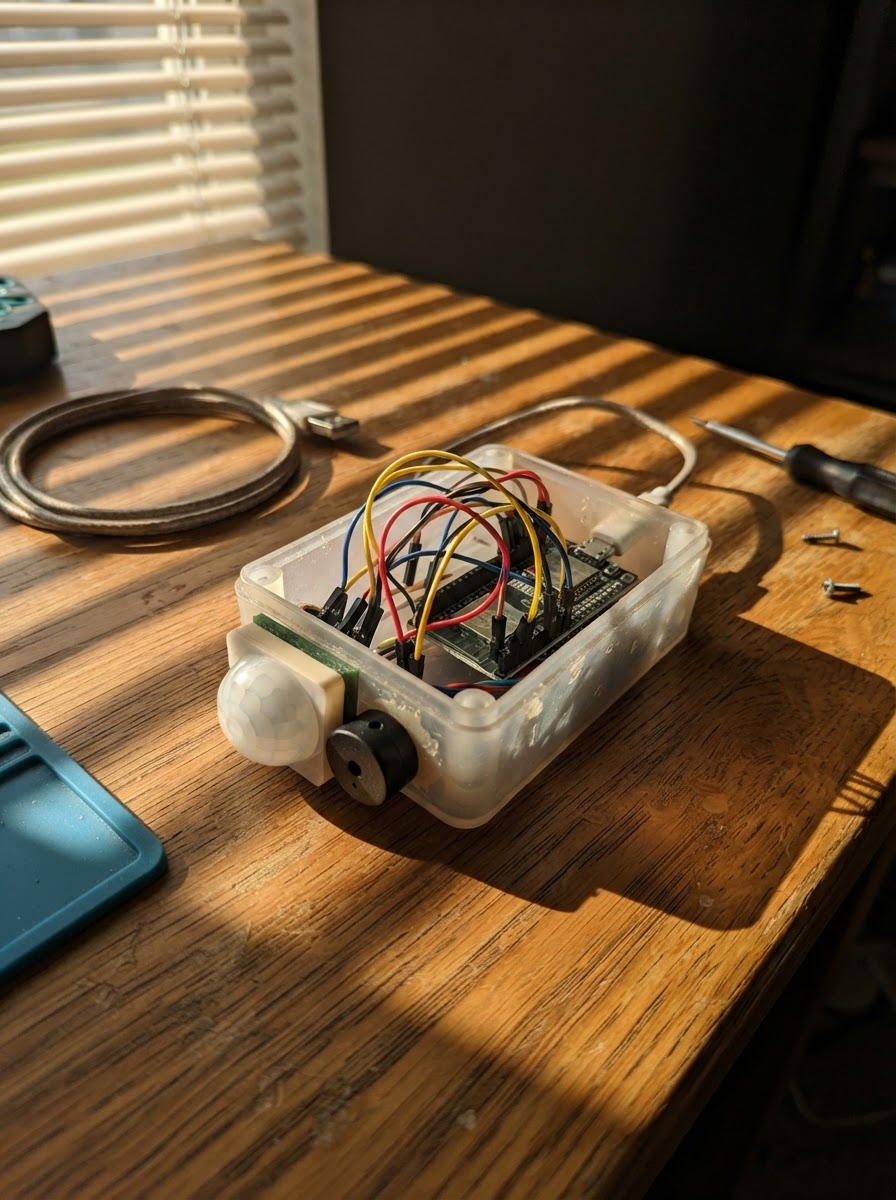
This project turns an ESP32 into a motion-activated alarm system that sends instant alerts via Telegram. When the HC-SR501 PIR sensor detects movement, the device triggers a buzzer and posts a notification to a Telegram chat, making it ideal for security monitoring, garage alerts, or motion-triggered notifications in any space.
The guide includes a complete wiring diagram showing how to connect the PIR sensor and buzzer to the ESP32, a full parts list, step-by-step assembly instructions, and ready-to-use firmware. After configuration with WiFi credentials and a Telegram bot token, the system is ready to monitor and alert.
Wiring diagram

Gather all the parts
Assemble it in 5 steps
1. Keep the ESP32 disconnected while wiring
Unplug the ESP32 USB cable before making or moving any connections.
- Use breadboard jumper wires and check each pin label before powering the circuit.
- Do not connect a 5 V wire to an ESP32 GPIO pin.
2. Connect the PIR sensor power
Connect pir_1 VCC to the ESP32 VIN/5V pin and pir_1 GND to an ESP32 GND pin.
- The HC-SR501 module accepts the board's 5 V VIN supply.
- VCC and GND reversed can damage the PIR module.
3. Connect the PIR signal directly
Connect pir_1 OUT directly to ESP32 GPIO27. No resistors are required for a normal HC-SR501 PIR module because its OUT pin uses approximately 3.3 V logic.
- Use the OUT pin, not the nearby sensitivity or delay adjustment controls.
- This direct connection applies to an HC-SR501 module. Do not directly connect an unknown 5 V-output sensor to GPIO27.
4. Connect the active buzzer
Connect buzzer_1 SIGNAL to ESP32 GPIO25 and buzzer_1 GND to ESP32 GND. This project assumes the specified 3.3 V active buzzer module.
- A shared GND connection is essential for the PIR and buzzer to work correctly.
- If your buzzer is marked 5 V only, do not power it from ESP32 3V3 or attach it directly without a transistor driver.
5. Power and test
Recheck all connections, then connect the ESP32 through USB. After deploying the firmware, leave the PIR still for 30–60 seconds while it stabilizes before testing motion.
- Set the PIR delay control low at first so it resets quickly between tests.
- Use Schematik's Deploy button after adding your Wi-Fi and Telegram credentials in the firmware.
- The project is USB powered; do not power the ESP32 from USB and a separate VIN supply at the same time.
Review all connections
1. Connections between "pir_1" and "ESP32"
2. Connections between "buzzer_1" and "ESP32"
Deploy the firmware
#include <Arduino.h>
#include <WiFi.h>
#include <WiFiClientSecure.h>
#include <HTTPClient.h>

// Enter the Wi-Fi network the ESP32 will use.

// Forward declarations
String urlEncode(const String &text);
bool telegramIsConfigured();
bool sendTelegramMessage(const String &message);
void connectWiFi();
void startAlarm();
void updateBuzzer();

const char *WIFI_SSID = "YOUR_WIFI_NAME";
const char *WIFI_PASSWORD = "YOUR_WIFI_PASSWORD";

// Create a bot with @BotFather in Telegram, then enter its token and your chat ID.
const char *TELEGRAM_BOT_TOKEN = "YOUR_BOT_TOKEN";
const char *TELEGRAM_CHAT_ID = "YOUR_CHAT_ID";

constexpr int PIR_PIN = 27;
constexpr int BUZZER_PIN = 25;
constexpr unsigned long ALERT_COOLDOWN_MS = 60000UL;
constexpr unsigned long BUZZ_DURATION_MS = 3000UL;

bool previousMotion = false;
bool buzzerOn = false;
unsigned long lastAlertMs = 0;
unsigned long buzzerStartedMs = 0;

String urlEncode(const String &text) {
  const char *hex = "0123456789ABCDEF";
  String encoded;
  encoded.reserve(text.length() * 3);
  for (size_t i = 0; i < text.length(); ++i) {
    const uint8_t c = static_cast<uint8_t>(text[i]);
    if ((c >= 'a' && c <= 'z') || (c >= 'A' && c <= 'Z') ||
        (c >= '0' && c <= '9') || c == '-' || c == '_' || c == '.' || c == '~') {
      encoded += static_cast<char>(c);
    } else {
      encoded += '%';
      encoded += hex[c >> 4];
      encoded += hex[c & 0x0F];
    }
  }
  return encoded;
}

bool telegramIsConfigured() {
  return String(TELEGRAM_BOT_TOKEN) != "YOUR_BOT_TOKEN" &&
         String(TELEGRAM_CHAT_ID) != "YOUR_CHAT_ID";
}

bool sendTelegramMessage(const String &message) {
  if (WiFi.status() != WL_CONNECTED || !telegramIsConfigured()) return false;

  WiFiClientSecure client;
  client.setInsecure();
  HTTPClient https;
  const String url = String("https://api.telegram.org/bot") + TELEGRAM_BOT_TOKEN +
                     "/sendMessage?chat_id=" + urlEncode(TELEGRAM_CHAT_ID) +
                     "&text=" + urlEncode(message);
  if (!https.begin(client, url)) return false;
  const int httpCode = https.GET();
  https.end();
  return httpCode == HTTP_CODE_OK;
}

void connectWiFi() {
  WiFi.mode(WIFI_STA);
  WiFi.begin(WIFI_SSID, WIFI_PASSWORD);
  Serial.print("Connecting to Wi-Fi");
  const unsigned long startMs = millis();
  while (WiFi.status() != WL_CONNECTED && millis() - startMs < 20000UL) {
    delay(250);
    Serial.print('.');
  }
  Serial.println();
  if (WiFi.status() == WL_CONNECTED) {
    Serial.print("Wi-Fi connected. IP: ");
    Serial.println(WiFi.localIP());
  } else {
    Serial.println("Wi-Fi not connected; local alarm works and Telegram will retry on the next event.");
  }
}

void startAlarm() {
  digitalWrite(BUZZER_PIN, HIGH);
  buzzerOn = true;
  buzzerStartedMs = millis();
}

void updateBuzzer() {
  if (buzzerOn && millis() - buzzerStartedMs >= BUZZ_DURATION_MS) {
    digitalWrite(BUZZER_PIN, LOW);
    buzzerOn = false;
  }
}

void setup() {
  Serial.begin(115200);
  pinMode(PIR_PIN, INPUT);
  pinMode(BUZZER_PIN, OUTPUT);
  digitalWrite(BUZZER_PIN, LOW);
  connectWiFi();
  Serial.println("Motion alarm ready. Let the PIR settle for 30-60 seconds after power-up.");
}

void loop() {
  updateBuzzer();
  const bool motionNow = digitalRead(PIR_PIN) == HIGH;
  const unsigned long now = millis();

  if (motionNow && !previousMotion && now - lastAlertMs >= ALERT_COOLDOWN_MS) {
    lastAlertMs = now;
    startAlarm();
    Serial.println("Motion detected: alarm started.");
    if (sendTelegramMessage("Motion detected by your ESP32 security alarm.")) {
      Serial.println("Telegram alert sent.");
    } else {
      Serial.println("Telegram alert not sent. Check Wi-Fi, token, chat ID, and start the bot chat.");
    }
  }
  previousMotion = motionNow;

  static unsigned long lastReconnectMs = 0;
  if (WiFi.status() != WL_CONNECTED && now - lastReconnectMs >= 30000UL) {
    lastReconnectMs = now;
    WiFi.disconnect();
    WiFi.begin(WIFI_SSID, WIFI_PASSWORD);
  }
  delay(20);
}
Remix this project
Make it yours in one click
Open a full copy of this project in your own Schematik workspace — diagram, code, parts, and assembly steps included. Swap the sensor, add features, or redesign the whole thing with AI. The author's original stays untouched.
Related projects

Create A Complete Electrical Schematic Esp32 Sma
ESP32 · September 17, 2026Ayansh Agrawal
ESP32 Kare Ekran Projeleri
ESP32 · September 16, 2026Seref Ai
Component Qty --------------------------- ------
ESP32 · September 16, 2026Yathartha Chakrawal