Community project
ESP32 Weather Display
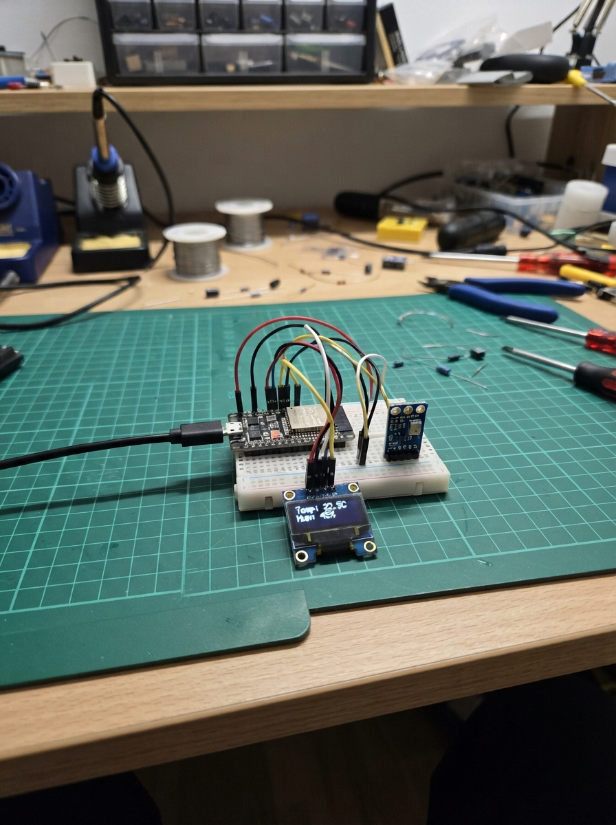
This project builds a compact room monitor that displays temperature, humidity, and atmospheric pressure on a small OLED screen. The ESP32 microcontroller reads environmental data from a BME280 sensor and updates the display in real time, making it perfect for tracking indoor conditions at a glance.
The guide includes a wiring diagram showing how to connect the BME280 and SSD1306 display to the ESP32 using I2C communication, a complete parts list, and ready-to-use firmware. Assembly takes just minutes—place the three components, connect power and ground, link the two shared signal wires, and power up to start monitoring.
Wiring diagram

Gather all the parts
Assemble it in 4 steps
1. Place the three parts
Put the ESP32 DevKit v1, the BME280 sensor board, and the small OLED screen where you can reach their printed pin labels. Keep the board unplugged while you connect the jumper wires.
- Both small boards use the same two signal wires, so their matching SDA pins can share one ESP32 pin and their matching SCL pins can share another.
- Do not connect power while moving wires; an accidental connection between 3V3 and GND can heat the board or damage a part.
2. Connect power and ground
Run one wire from ESP32 3V3 to BME280 VCC (power), and one wire from ESP32 GND to BME280 GND (ground). Then run ESP32 3V3 to OLED VCC (power), and ESP32 GND to OLED GND (ground).
- Use red wires for both 3V3 connections and black wires for both GND connections so they are easy to check.
- Make sure VCC and GND are not swapped on either small board — swapped power can damage the sensor or screen.
3. Connect the two shared signal wires
Connect ESP32 GPIO21 to BME280 SDA (data) and OLED SDA (data). Connect ESP32 GPIO22 to BME280 SCL (clock) and OLED SCL (clock). Use a breadboard row or two jumper wires from each ESP32 pin so each signal reaches both small boards.
- The labels may read SDI instead of SDA and SCK instead of SCL on some BME280 boards; those are the same two connections for this project.
- Do not connect the sensor's optional SDO pin for this build; leaving it alone keeps its normal address and avoids an unnecessary wire.
4. Power up the monitor
Check every connection against the printed labels one last time, then plug the ESP32 into your computer with USB. The screen should show a starting message after it is flashed.
- If the screen stays blank after deployment, first recheck its VCC, GND, SDA, and SCL labels rather than moving random wires.
- Only use the ESP32's 3V3 pin for these two small boards in this design; connecting their VCC pins to a higher voltage is unnecessary.
Review all connections
1. Connections between "bme280_1" and "ESP32"
2. Connections between "oled_1" and "ESP32"
Deploy the firmware
#include <Arduino.h>
#include <Wire.h>
#include <Adafruit_BME280.h>
#include <Adafruit_GFX.h>
#include <Adafruit_SSD1306.h>


// Forward declarations
void showMessage(const char *line1, const char *line2);
void drawReadings(float temperature, float humidity, float pressureHpa);

constexpr int I2C_SDA_PIN = 21;
constexpr int I2C_SCL_PIN = 22;
constexpr uint8_t SCREEN_WIDTH = 128;
constexpr uint8_t SCREEN_HEIGHT = 64;
constexpr uint8_t OLED_ADDRESS = 0x3C;

Adafruit_BME280 bme;
Adafruit_SSD1306 display(SCREEN_WIDTH, SCREEN_HEIGHT, &Wire, -1);

float lastTemperature = NAN;
float lastHumidity = NAN;
float lastPressure = NAN;
unsigned long lastSampleMs = 0;

void showMessage(const char *line1, const char *line2) {
  display.clearDisplay();
  display.setTextColor(SSD1306_WHITE);
  display.setTextSize(1);
  display.setCursor(0, 12);
  display.println(line1);
  display.setCursor(0, 30);
  display.println(line2);
  display.display();
}

void drawReadings(float temperature, float humidity, float pressureHpa) {
  display.clearDisplay();
  display.setTextColor(SSD1306_WHITE);
  display.setTextSize(1);
  display.setCursor(0, 0);
  display.println("ROOM MONITOR");
  display.drawFastHLine(0, 11, SCREEN_WIDTH, SSD1306_WHITE);

  display.setCursor(0, 18);
  display.print("Temp: ");
  display.print(temperature, 1);
  display.println(" C");

  display.setCursor(0, 33);
  display.print("Humidity: ");
  display.print(humidity, 0);
  display.println(" %");

  display.setCursor(0, 48);
  display.print("Pressure: ");
  display.print(pressureHpa, 0);
  display.println(" hPa");
  display.display();
}

void setup() {
  Serial.begin(115200);
  Wire.begin(I2C_SDA_PIN, I2C_SCL_PIN);

  if (!display.begin(SSD1306_SWITCHCAPVCC, OLED_ADDRESS)) {
    Serial.println("OLED not found");
    return;
  }
  showMessage("Room monitor", "Starting sensor...");

  if (!bme.begin(0x77)) {
    Serial.println("BME280 not found at 0x77");
    showMessage("Sensor not found", "Check BME280 wires");
    while (true) {
      delay(1000);
    }
  }
}

void loop() {
  if (millis() - lastSampleMs < 2000) {
    return;
  }
  lastSampleMs = millis();

  const float temperature = bme.readTemperature();
  const float humidity = bme.readHumidity();
  const float pressureHpa = bme.readPressure() / 100.0F;

  if (isnan(temperature) || isnan(humidity) || isnan(pressureHpa)) {
    showMessage("Sensor read error", "Check connections");
    return;
  }

  if (isnan(lastTemperature) || fabsf(temperature - lastTemperature) >= 0.1F ||
      fabsf(humidity - lastHumidity) >= 1.0F ||
      fabsf(pressureHpa - lastPressure) >= 1.0F) {
    drawReadings(temperature, humidity, pressureHpa);
    lastTemperature = temperature;
    lastHumidity = humidity;
    lastPressure = pressureHpa;
  }
}
Remix this project
Make it yours in one click
Open a full copy of this project in your own Schematik workspace — diagram, code, parts, and assembly steps included. Swap the sensor, add features, or redesign the whole thing with AI. The author's original stays untouched.
Related projects

Create A Complete Electrical Schematic Esp32 Sma
ESP32 · September 17, 2026Ayansh Agrawal
ESP32 Kare Ekran Projeleri
ESP32 · September 16, 2026Seref Ai
Component Qty --------------------------- ------
ESP32 · September 16, 2026Yathartha Chakrawal