Community project
ESP32 Wireless Control Remote
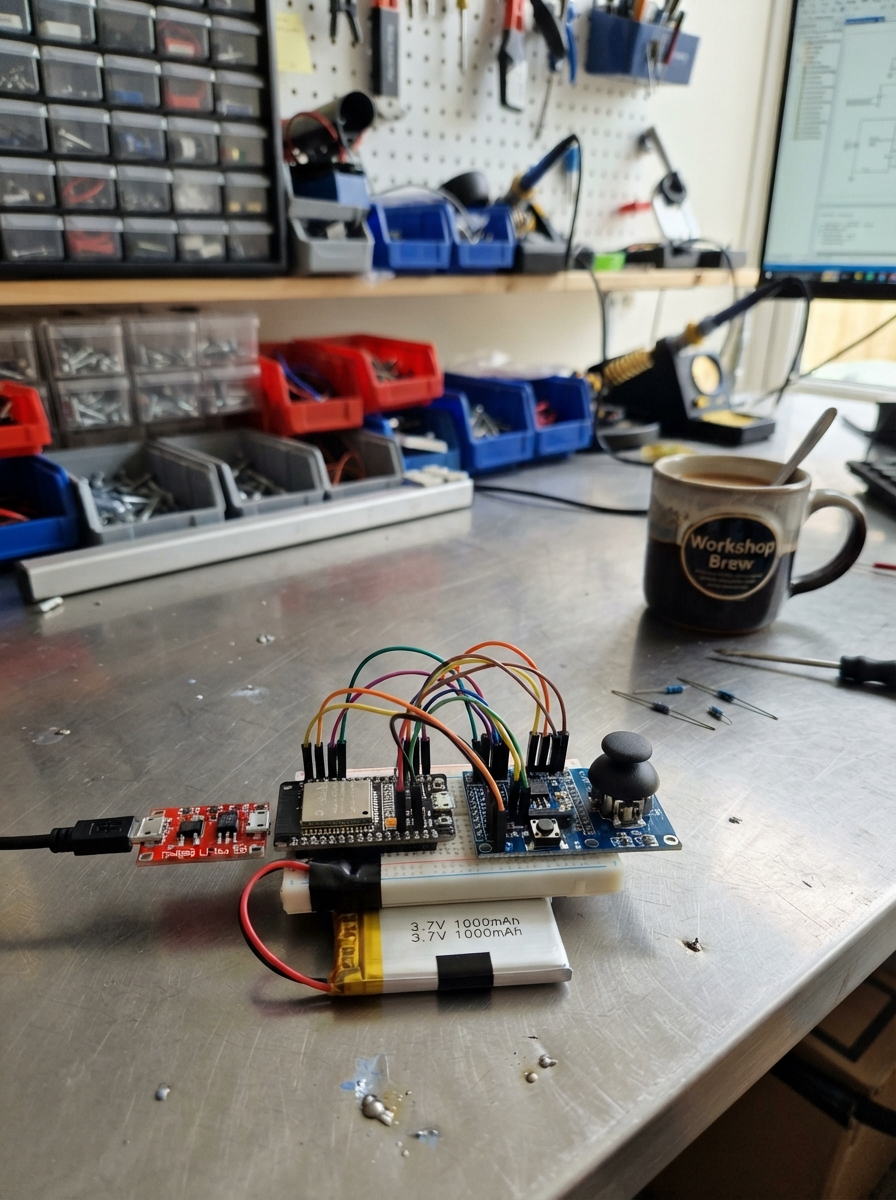
This wireless control remote uses an ESP32 to transmit joystick and button inputs over ESP-NOW, a low-latency wireless protocol. The remote is powered by a rechargeable LiPo battery with integrated charging and protection, stepped up to 5V for the I/O expander while the ESP32 runs on 3.3V. The guide provides a complete wiring diagram, parts list, and step-by-step assembly instructions to build a 14-button remote with dual-axis joystick control.
The firmware samples the analog joystick with deadband filtering and reads 14 digital buttons through an MCP23017 I2C expander, packaging the data into compact wireless packets. Assembly follows a logical progression from power distribution through sensor integration, with a pre-power inspection checklist to ensure safe operation.
Wiring diagram

Gather all the parts
Assemble it in 8 steps
1. Make the battery and charger connection
With no USB cable connected, connect lipo_1 +V to tp4056_1 B+ and lipo_1 GND to tp4056_1 B-. Use the battery connector’s red wire for positive and black wire for negative.
- The TP4056 IN+ and IN- terminals are only for a 5 V USB charging lead, not the battery.
- Do not reverse the LiPo leads — a reversed lithium battery connection can destroy the charger module or cause the battery to overheat.
2. Add the safe 5 V board supply
Connect tp4056_1 OUT+ to boost_5v_1 VIN, and tp4056_1 OUT- to boost_5v_1 GND. Connect boost_5v_1 VOUT to the ESP32 5V/VIN pin. The boost module raises the battery’s changing voltage to the steady 5 V the ESP32 DevKit input expects.
- Before attaching the ESP32, use a meter to confirm the boost module output is close to 5 V.
- Do not connect TP4056 OUT+ straight to the ESP32 5V/VIN pin — a single LiPo is only about 3.0–4.2 V and the board can become unreliable.
3. Build the shared ground and 3.3 V rails
Connect an ESP32 GND pin to the common ground rail. Use the ESP32 3V3 pin as the separate 3.3 V rail for the joystick, MCP23017, and reset resistor. Keep the 5 V VIN rail separate from the 3.3 V logic rail.
- Every module must have a path back to the same ground rail or its signal wires cannot be read correctly.
- Never feed the 5 V boost output into the ESP32 3V3 pin — this can damage the ESP32 and the 3.3 V modules.
4. Wire the MCP23017 expander
Connect mcp23017_1 VDD to ESP32 3V3, VSS to GND, SDA to GPIO21, and SCL to GPIO22. Connect A0, A1, and A2 each to GND; this selects address 0x20. Connect one end of reset_resistor_1 to MCP23017 RESET and its other end to 3V3.
- Use a short pair of wires for SDA and SCL. Many MCP23017 breakout boards already include I2C pull-up resistors.
- Make sure the expander is powered from 3.3 V, not 5 V — 5 V I2C signals can damage the ESP32 pins.
5. Wire the pan and tilt joystick
Connect joystick_1 VCC to ESP32 3V3, GND to GND, VRx to GPIO34, and VRy to GPIO35. Leave the joystick SW pin unconnected because this design already has fourteen separate buttons.
- GPIO34 and GPIO35 are input-only pins, which makes them a good fit for the joystick’s two analog readings.
- Keep the joystick VCC on 3.3 V — powering it from 5 V would put too much voltage on the ESP32 analog inputs.
6. Wire buttons 1 through 8
Connect one leg of button_1 through button_8 together on the ground rail. Connect the other leg of button_1 to mcp23017_1 GPA0, button_2 to GPA1, button_3 to GPA2, button_4 to GPA3, button_5 to GPA4, button_6 to GPA5, button_7 to GPA6, and button_8 to GPA7.
- For four-legged tactile switches, use two legs from opposite sides; two legs on the same side are already joined inside the switch.
- Do not attach these button lines to 3.3 V — the firmware turns on pull-ups inside the MCP23017, and each press must connect its line to ground.
7. Wire buttons 9 through 14
Connect one leg of button_9 through button_14 to the same ground rail. Connect each remaining signal leg to mcp23017_1 GPB0, GPB1, GPB2, GPB3, GPB4, and GPB5 in button-number order.
- Label each switch wire while building so the action assigned in the receiver can match the physical button.
- Do not use GPB6 or GPB7 for this fourteen-button version unless you also update the firmware.
8. Inspect before applying power
Check that every black ground wire joins the common ground rail, the ESP32 receives 5 V only on its 5V/VIN pin, and the MCP23017 plus joystick receive 3.3 V only. Put the remote inside a non-conductive enclosure before vehicle use and keep it away from heat, water, and moving controls.
- The ESP32’s built-in Wi-Fi hardware sends the control packet; this master unit needs no separate radio module.
- This transmitter is not a safety-rated automotive control system. Do not use it for steering, braking, throttle, airbags, or any function where a missed or unwanted command could injure someone.
Review all connections
1. Connections between "lipo_1" and "ESP32"
2. Connections between "tp4056_1" and "ESP32"
3. Connections between "boost_5v_1" and "ESP32"
4. Connections between "mcp23017_1" and "ESP32"
5. Connections between "reset_resistor_1" and "ESP32"
6. Connections between "joystick_1" and "ESP32"
7. Connections between "button_1" and "ESP32"
8. Connections between "button_2" and "ESP32"
9. Connections between "button_3" and "ESP32"
10. Connections between "button_4" and "ESP32"
11. Connections between "button_5" and "ESP32"
12. Connections between "button_6" and "ESP32"
13. Connections between "button_7" and "ESP32"
14. Connections between "button_8" and "ESP32"
15. Connections between "button_9" and "ESP32"
16. Connections between "button_10" and "ESP32"
17. Connections between "button_11" and "ESP32"
18. Connections between "button_12" and "ESP32"
19. Connections between "button_13" and "ESP32"
20. Connections between "button_14" and "ESP32"
Deploy the firmware
#include <Arduino.h>
#include <Wire.h>
#include <WiFi.h>
#include <esp_now.h>
#include <Adafruit_MCP23X17.h>
constexpr uint8_t I2C_SDA_PIN = 21;
constexpr uint8_t I2C_SCL_PIN = 22;
constexpr uint8_t JOYSTICK_X_PIN = 34;
constexpr uint8_t JOYSTICK_Y_PIN = 35;
constexpr uint8_t MCP_ADDRESS = 0x20;
constexpr uint32_t SAMPLE_INTERVAL_MS = 20;
constexpr uint32_t KEEPALIVE_INTERVAL_MS = 250;
constexpr int JOYSTICK_DEADBAND = 24;
Adafruit_MCP23X17 mcp;
const uint8_t broadcastAddress[] = {0xFF, 0xFF, 0xFF, 0xFF, 0xFF, 0xFF};
struct __attribute__((packed)) RemotePacket {
uint16_t sequence;
uint16_t joystickX;
uint16_t joystickY;
uint16_t buttons;
};
RemotePacket currentPacket{};
RemotePacket lastSentPacket{};
uint32_t lastSampleMs = 0;
uint32_t lastSendMs = 0;
bool haveSentPacket = false;
bool packetsEqual(const RemotePacket &a, const RemotePacket &b) {
return a.joystickX == b.joystickX &&
a.joystickY == b.joystickY &&
a.buttons == b.buttons;
}
uint16_t readButtons() {
uint16_t pressedMask = 0;
for (uint8_t pin = 0; pin < 14; ++pin) {
if (mcp.digitalRead(pin) == LOW) {
pressedMask |= (1U << pin);
}
}
return pressedMask;
}
uint16_t stabilizedAnalogRead(uint8_t pin) {
uint16_t first = analogRead(pin);
uint16_t second = analogRead(pin);
return (first + second) / 2;
}
bool joystickChanged(uint16_t a, uint16_t b) {
return abs((int)a - (int)b) > JOYSTICK_DEADBAND;
}
void sendPacket() {
currentPacket.sequence++;
const esp_err_t result = esp_now_send(broadcastAddress,
reinterpret_cast<const uint8_t *>(¤tPacket),
sizeof(currentPacket));
if (result == ESP_OK) {
lastSentPacket = currentPacket;
lastSendMs = millis();
haveSentPacket = true;
}
}
void setup() {
Serial.begin(115200);
Wire.begin(I2C_SDA_PIN, I2C_SCL_PIN);
if (!mcp.begin_I2C(MCP_ADDRESS, &Wire)) {
Serial.println("MCP23017 not found at 0x20");
while (true) {
delay(1000);
}
}
for (uint8_t pin = 0; pin < 14; ++pin) {
mcp.pinMode(pin, INPUT_PULLUP);
}
analogReadResolution(12);
WiFi.mode(WIFI_STA);
if (esp_now_init() != ESP_OK) {
Serial.println("ESP-NOW initialization failed");
while (true) {
delay(1000);
}
}
esp_now_peer_info_t peerInfo{};
memcpy(peerInfo.peer_addr, broadcastAddress, sizeof(broadcastAddress));
peerInfo.channel = 0;
peerInfo.encrypt = false;
if (esp_now_add_peer(&peerInfo) != ESP_OK) {
Serial.println("ESP-NOW broadcast peer setup failed");
while (true) {
delay(1000);
}
}
currentPacket.joystickX = stabilizedAnalogRead(JOYSTICK_X_PIN);
currentPacket.joystickY = stabilizedAnalogRead(JOYSTICK_Y_PIN);
currentPacket.buttons = readButtons();
sendPacket();
}
void loop() {
const uint32_t now = millis();
if (now - lastSampleMs < SAMPLE_INTERVAL_MS) {
return;
}
lastSampleMs = now;
RemotePacket nextPacket = currentPacket;
nextPacket.joystickX = stabilizedAnalogRead(JOYSTICK_X_PIN);
nextPacket.joystickY = stabilizedAnalogRead(JOYSTICK_Y_PIN);
nextPacket.buttons = readButtons();
const bool changed = nextPacket.buttons != currentPacket.buttons ||
joystickChanged(nextPacket.joystickX, currentPacket.joystickX) ||
joystickChanged(nextPacket.joystickY, currentPacket.joystickY);
currentPacket = nextPacket;
if (changed || !haveSentPacket || now - lastSendMs >= KEEPALIVE_INTERVAL_MS) {
sendPacket();
}
}Remix this project
Make it yours in one click
Open a full copy of this project in your own Schematik workspace — diagram, code, parts, and assembly steps included. Swap the sensor, add features, or redesign the whole thing with AI. The author's original stays untouched.