Community project
Low-Cost Pest-Detecting Car
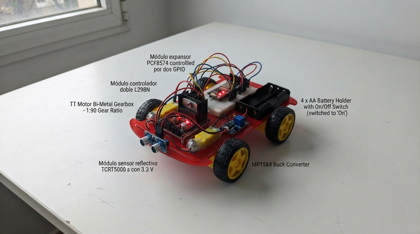
This low-cost pest-detecting car is an autonomous rover built around an ESP32 microcontroller that patrols surfaces using infrared sensors to detect movement and activity. The robot combines a dual-motor drive system with a reflective sensor module, powered by AA batteries and regulated through a buck converter, creating an affordable platform for monitoring and detection tasks.
Builders will receive a complete wiring diagram showing connections between the ESP32, L298N motor controller, PCF8574 I2C expander, TCRT5000 sensor, and TT motors with gearbox. The guide includes a full parts list, step-by-step assembly instructions, and firmware with web server capabilities for remote monitoring and control via WiFi.
Wiring diagram

Gather all the parts
Assemble it in 6 steps
1. Reúne y prepara el carro
Necesitas un chasis 4WD como el de la foto: base, cuatro motores TT de 3–6 V, cuatro ruedas, soportes y tornillos. También necesitas la ESP32-CAM con su base ESP32-CAM-MB, un L298N, un PCF8574, un sensor TCRT5000 que indique que funciona a 3.3 V, un portapilas de cuatro AA con interruptor, cuatro pilas AA, un regulador MP1584, cables Dupont, cinta de doble cara o bridas y una caja o vaso plástico pequeño para proteger la cámara.
- El chasis puede ser igual al de la imagen aunque su antena o su placa original no se usen.
- Guarda cualquier placa receptora de control remoto que viniera con el carro: este proyecto usa la ESP32-CAM y el L298N en su lugar.
- No pongas las pilas todavía; así ningún motor puede arrancar mientras el grupo cablea el carro.
2. Monta los motores y las ruedas
Atornilla un motor en cada esquina de la base. Coloca las dos ruedas del lado izquierdo en motor_delantero_izq y motor_trasero_izq, y las dos ruedas del lado derecho en motor_delantero_der y motor_trasero_der. Pon la ESP32-CAM delante y alta, con su lente mirando al suelo y unos centímetros hacia delante.
- Deja los cables de los motores lo bastante largos para poder cambiar una rueda sin arrancarlos.
- Una tira de cartón negro alrededor de la cámara reduce los reflejos de la luz.
- Mantén dedos, pelo y cables lejos de las ruedas: un motor puede girar de golpe durante una prueba.
3. Conecta las ruedas al controlador
Une M1 de motor_delantero_izq y M1 de motor_trasero_izq a OUT1 del control_motores (potencia del lado izquierdo). Une sus terminales M2 a OUT2 (potencia del lado izquierdo). Une M1 de motor_delantero_der y M1 de motor_trasero_der a OUT3 (potencia del lado derecho), y sus M2 a OUT4 (potencia del lado derecho). Si un lado gira hacia atrás en la primera prueba, intercambia solamente sus dos cables en OUT1/OUT2 o en OUT3/OUT4.
- Usa un color para el primer terminal de cada motor y otro color para el segundo; facilita encontrar una rueda invertida.
- No conectes los cables de un motor a la ESP32-CAM: los motores necesitan el L298N porque consumen mucha más corriente.
4. Cablea la alimentación con el interruptor apagado
Conecta el cable rojo VOUT de bateria_carro a VS de control_motores (potencia de los motores) y también a VIN de regulador_5v (entrada de energía). Conecta el cable negro GND de bateria_carro a GND de control_motores y a GND de regulador_5v (tierra compartida). Ajusta regulador_5v a exactamente 5.0 V con un multímetro antes de conectar nada más. Conecta VOUT de regulador_5v al pin 5V de la ESP32-CAM-MB y al pin 5V de control_motores (alimentación).
- Deja puestos los dos puentes ENA y ENB del L298N; hacen que ambos lados del carro puedan avanzar.
- En los L298N con un puente marcado 5V-EN, quítalo antes de alimentar el pin 5V desde el regulador; así no unes dos fuentes de energía distintas.
- Si el regulador no marca 5.0 V antes de conectarlo a la ESP32-CAM, detente: un ajuste demasiado alto puede dañar la cámara.
- Todos los GND deben estar unidos; si falta uno, el carro puede moverse de forma impredecible o no responder.
5. Conecta el sensor y la plaquita de control
Une VCC de sensor_entrada a 3.3V de la ESP32-CAM (power), GND a GND (ground) y DO a GPIO3 (signal). Une VCC de expansor_gpio a 3.3V (power), GND a GND (ground), SDA a GPIO13 (data) y SCL a GPIO14 (data). Une P0, P1, P2 y P3 de expansor_gpio, en ese orden, a IN1, IN2, IN3 e IN4 de control_motores (señales).
- Fija el sensor bajo la parte delantera, a 1–2 cm del suelo y sin mirar directamente al sol.
- Pega una pequeña tarjeta blanca bajo el sensor para comprobar su tornillo azul: retírala para ver que el estado cambia.
- El TCRT5000 debe ser una versión compatible con 3.3 V; un módulo que saque 5 V por DO puede estropear GPIO3.
- No conectes el PCF8574 a 5 V: sus cuatro salidas irían a entradas de 3.3 V del L298N y sus cables I2C quedarían a un voltaje inseguro para la ESP32-CAM.
6. Enciende, despliega y prueba en el suelo
Comprueba que el carro está elevado sobre un libro para que las ruedas no toquen la mesa. Conecta la ESP32-CAM-MB por USB, pulsa Deploy y después enciende el portapilas. Con un teléfono, entra a la red Wi-Fi Carro-Plagas con la clave plagas123. Pulsa “Iniciar recorrido”; el carro avanza un máximo de 20 segundos o se detiene cuando el sensor ve algo. Pulsa “Tomar foto” para revisar lo encontrado.
- Haz la primera prueba sin tierra ni plantas; una cartulina o un juguete pequeño es más fácil de recuperar.
- Cuando ya avance recto, prueba sobre una bandeja o pasillo despejado y siempre acompañado por un adulto.
- No uses el carro cerca de escaleras, agua, mascotas o plantas delicadas; se mueve de forma sencilla y no esquiva obstáculos.
Review all connections
1. Connections between "sensor_entrada" and "ESP32"
2. Connections between "expansor_gpio" and "ESP32"
3. Connections between "control_motores" and "ESP32"
4. Connections between "bateria_carro" and "ESP32"
5. Connections between "regulador_5v" and "ESP32"
Deploy the firmware
#include <Arduino.h>
#include <Wire.h>
#include <WiFi.h>
#include <WebServer.h>
#include "esp_camera.h"

const char *AP_NAME = "Carro-Plagas";
const char *AP_PASSWORD = "plagas123";

#define IR_SENSOR_PIN 3
#define I2C_SDA_PIN 13
#define I2C_SCL_PIN 14
#define FLASH_LED_PIN 4
const uint8_t PCF8574_ADDRESS = 0x20;
const unsigned long MAX_DRIVE_MS = 20000;

#define PWDN_GPIO_NUM 32
#define RESET_GPIO_NUM -1
#define XCLK_GPIO_NUM 0
#define SIOD_GPIO_NUM 26
#define SIOC_GPIO_NUM 27
#define Y9_GPIO_NUM 35
#define Y8_GPIO_NUM 34
#define Y7_GPIO_NUM 39
#define Y6_GPIO_NUM 36
#define Y5_GPIO_NUM 21
#define Y4_GPIO_NUM 19
#define Y3_GPIO_NUM 18
#define Y2_GPIO_NUM 5
#define VSYNC_GPIO_NUM 25
#define HREF_GPIO_NUM 23
#define PCLK_GPIO_NUM 22

WebServer server(80);
bool activitySeen = false, flashOn = false, driving = false;
int lastSensorState = HIGH;
unsigned long lastChangeMs = 0, driveStartedMs = 0;

void writeMotorByte(uint8_t value) { Wire.beginTransmission(PCF8574_ADDRESS); Wire.write(value); Wire.endTransmission(); }
void stopCar() { writeMotorByte(0x00); driving = false; }
void driveForward() { writeMotorByte(0x05); driving = true; driveStartedMs = millis(); }
void setFlash(bool on) { flashOn = on; digitalWrite(FLASH_LED_PIN, on ? HIGH : LOW); }

void sendHome() {
  String page = R"HTML(<!doctype html><html lang="es"><head><meta name="viewport" content="width=device-width,initial-scale=1"><title>Carro detector de plagas</title><style>body{font-family:Arial;margin:22px;background:#f4f7ed;color:#20331c}button{font-size:17px;padding:12px;margin:4px;border-radius:8px;border:0;background:#5b842f;color:white}.stop{background:#a33}img{max-width:100%;border-radius:8px;border:3px solid #5b842f}</style></head><body><h1>Carro detector de plagas</h1><p id="state">Leyendo...</p><button onclick="go()">Iniciar recorrido</button><button class="stop" onclick="stop()">Detener carro</button><button onclick="foto()">Tomar foto</button><button onclick="flash()">Encender/apagar luz</button><p><img id="photo" alt="La foto aparecerá aquí"></p><p>El carro se detiene si el sensor nota algo muy cerca. Revisa la foto: el sensor no identifica especies por sí solo.</p><script>async function estado(){let r=await fetch('/status');let j=await r.json();document.getElementById('state').textContent=j.driving?'El carro avanza despacio':(j.activity?'Actividad detectada: carro detenido':'Carro detenido, listo');}async function go(){await fetch('/go');estado();}async function stop(){await fetch('/stop');estado();}function foto(){document.getElementById('photo').src='/capture?t='+Date.now();}async function flash(){await fetch('/flash');}setInterval(estado,700);estado();</script></body></html>)HTML";
  server.send(200, "text/html; charset=utf-8", page);
}
void sendStatus() { String json = String("{\"activity\":") + (activitySeen ? "true" : "false") + ",\"driving\":" + (driving ? "true" : "false") + "}"; server.send(200, "application/json", json); }
void capturePhoto() { camera_fb_t *frame = esp_camera_fb_get(); if (!frame) { server.send(503, "text/plain", "La camara no pudo tomar una foto"); return; } server.sendHeader("Content-Disposition", "inline; filename=foto.jpg"); server.setContentLength(frame->len); server.send(200, "image/jpeg", ""); server.client().write(frame->buf, frame->len); esp_camera_fb_return(frame); }

bool startCamera() {
  camera_config_t config; config.ledc_channel=LEDC_CHANNEL_0; config.ledc_timer=LEDC_TIMER_0; config.pin_d0=Y2_GPIO_NUM; config.pin_d1=Y3_GPIO_NUM; config.pin_d2=Y4_GPIO_NUM; config.pin_d3=Y5_GPIO_NUM; config.pin_d4=Y6_GPIO_NUM; config.pin_d5=Y7_GPIO_NUM; config.pin_d6=Y8_GPIO_NUM; config.pin_d7=Y9_GPIO_NUM; config.pin_xclk=XCLK_GPIO_NUM; config.pin_pclk=PCLK_GPIO_NUM; config.pin_vsync=VSYNC_GPIO_NUM; config.pin_href=HREF_GPIO_NUM; config.pin_sscb_sda=SIOD_GPIO_NUM; config.pin_sscb_scl=SIOC_GPIO_NUM; config.pin_pwdn=PWDN_GPIO_NUM; config.pin_reset=RESET_GPIO_NUM; config.xclk_freq_hz=20000000; config.pixel_format=PIXFORMAT_JPEG; config.frame_size=FRAMESIZE_VGA; config.jpeg_quality=12; config.fb_count=psramFound()?2:1; return esp_camera_init(&config)==ESP_OK;
}

void setup() {
  pinMode(IR_SENSOR_PIN, INPUT); pinMode(FLASH_LED_PIN, OUTPUT); setFlash(false);
  Wire.begin(I2C_SDA_PIN, I2C_SCL_PIN); stopCar();
  if (!startCamera()) return;
  WiFi.mode(WIFI_AP); WiFi.softAP(AP_NAME, AP_PASSWORD);
  server.on("/", HTTP_GET, sendHome); server.on("/status", HTTP_GET, sendStatus); server.on("/capture", HTTP_GET, capturePhoto);
  server.on("/go", HTTP_GET, [](){ activitySeen=false; driveForward(); server.send(200,"text/plain","Recorrido iniciado"); });
  server.on("/stop", HTTP_GET, [](){ stopCar(); server.send(200,"text/plain","Carro detenido"); });
  server.on("/flash", HTTP_GET, [](){ setFlash(!flashOn); server.send(200,"text/plain",flashOn?"Luz encendida":"Luz apagada"); });
  server.begin();
}
void loop() {
  server.handleClient(); int sensorState=digitalRead(IR_SENSOR_PIN);
  if (sensorState!=lastSensorState && millis()-lastChangeMs>80) { lastChangeMs=millis(); lastSensorState=sensorState; if (sensorState==LOW && driving) { activitySeen=true; stopCar(); } }
  if (driving && millis()-driveStartedMs>=MAX_DRIVE_MS) stopCar();
}
Remix this project
Make it yours in one click
Open a full copy of this project in your own Schematik workspace — diagram, code, parts, and assembly steps included. Swap the sensor, add features, or redesign the whole thing with AI. The author's original stays untouched.