Community project
ESP32 Automotive Light Servo Controller
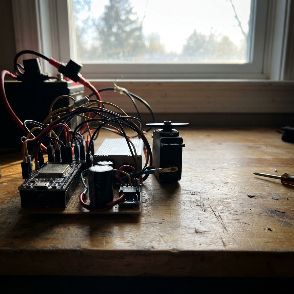
This project builds a 12 V automotive light servo controller using an ESP32 to manage auxiliary lighting, laser modules, and pan-tilt servo positioning. The system safely interfaces with vehicle power through fused battery connections, surge protection, and a dedicated buck converter, making it suitable for automotive environments where reliability and protection are critical.
The guide provides a complete wiring diagram, parts list, and step-by-step assembly instructions to connect the MG996R servos, auxiliary light, laser relay, and control electronics. Firmware is included to enable serial command control over pan angle, tilt angle, main light state, and laser activation, with safety checks and status reporting built in.
Wiring diagram

Gather all the parts
Assemble it in 6 steps
1. Make the battery connection safe
With the vehicle battery disconnected, place the 10 A inline fuse holder in the positive battery lead as close to the battery as practical. Connect battery positive to fuse IN, then connect fuse OUT to the anode of the high-current reverse-polarity diode. Connect the battery negative lead to the common chassis-ground point.
- Use wire and crimp terminals rated for the fuse current, and secure the fuse holder so it cannot rub on metal.
- Do not use the requested 1N4007 in this series power path: it is only a 1 A diode and can overheat or fail with the servo load.
- Remove the fuse or disconnect the battery before changing any wiring; a vehicle battery can deliver enough current to melt wires.
2. Add surge protection and the 5-volt converter
Connect the reverse-polarity diode cathode to the protected 12-volt distribution point. Connect the 1.5KE18A TVS diode with its cathode to that protected 12-volt point and its anode to the common chassis ground. Connect the 5 V / 8 A buck converter IN+ to the protected 12-volt point and IN- to ground. Before connecting any electronics, adjust and measure its output as 5.0 V; then connect OUT+ to the 5 V rail and OUT- to ground.
- Keep the TVS leads and the buck converter input wires short because short wiring gives spikes less room to reach the electronics.
- A reversed TVS diode or a buck converter set above 5 V can damage the ESP32, servos, and relay.
- The 5 V converter must be genuinely rated for the servo surge current; an ordinary LM2596 module is typically only a 3 A regulator and is not adequate for two MG996R servos.
3. Power the ESP32 and servos
Connect the buck converter 5 V OUT+ rail to the ESP32 VIN/5V pin and connect OUT- to an ESP32 GND pin. Connect each servo red VCC wire to 5 V and each brown/black GND wire to the same common ground. Place the 1000 µF capacitor physically close to the servo connectors: its positive lead goes to 5 V and its striped negative lead goes to ground. Connect the pan servo orange signal wire to GPIO18 and the tilt servo orange signal wire to GPIO19.
- Use thicker, short paired power wires for the servos; thin breadboard jumper wires can cause the voltage to dip when the servos move.
- The ESP32 signals are GPIO18 → pan servo (signal) and GPIO19 → tilt servo (signal).
- Make sure the capacitor's striped negative lead goes to ground — reversing an electrolytic capacitor can make it burst.
- Never feed 12 V into the ESP32 VIN/5V pin or either servo power wire.
4. Wire the main auxiliary light switch
Connect the AOD4184 module VIN+ to the protected 12-volt distribution point and VIN- to common ground. Connect its small GND control pin to ESP32 ground and its SIG/PWM control pin to ESP32 GPIO21. Connect the module OUT+ and OUT- terminals to the matching positive and negative leads of the 12 V main auxiliary light.
- GPIO21 → SIG/PWM (control); VIN+ and VIN- supply the light-switch module; OUT+ and OUT- go only to the main light.
- Do not connect the light directly to GPIO21; the ESP32 pin supplies a tiny control signal, not lamp power.
- Confirm the light current is within the MOSFET module, fuse, wire, and connector ratings before fitting the fuse.
5. Wire the laser relay and laser light
Connect the relay module VCC to 5 V and GND to common ground. Connect relay IN to ESP32 GPIO22. Connect relay COM to the protected 12-volt distribution point, connect relay NO to the laser light positive lead, and connect the laser light negative lead to common ground.
- GPIO22 → relay IN (control); COM is the incoming 12 V; NO sends 12 V to the laser only when the relay is turned on.
- Some relay modules turn on when their IN pin is low. Test with the laser disconnected first; if its behavior is reversed, change RELAY_ACTIVE_HIGH in the firmware.
- Do not point the laser at eyes, people, vehicles, or reflective surfaces; secure it so it cannot move unexpectedly.
6. Inspect before applying vehicle power
Check every ground connection returns to the same chassis-ground point and that no bare positive conductor can touch the vehicle body. With the fuse removed, inspect polarity and measure for no short between the protected 12-volt point and ground. Then install the fuse, power the system, and verify the buck converter remains at 5.0 V while each servo moves.
- Keep the ESP32 and signal wiring away from ignition wiring, alternator wiring, and high-current lamp cables to reduce electrical noise.
- Do not test this unprotected circuit on public roads or connect it to any safety-critical vehicle function.
- If the 5 V rail falls below about 5 V or the ESP32 restarts while a servo moves, disconnect power and improve the 5 V supply capacity and servo wiring before continuing.
Review all connections
1. Connections between "car_battery_12v" and "ESP32"
2. Connections between "fuse_10a" and "ESP32"
3. Connections between "reverse_polarity_diode" and "ESP32"
4. Connections between "tvs_1_5ke18a" and "ESP32"
5. Connections between "buck_5v_8a" and "ESP32"
6. Connections between "servo_pan" and "ESP32"
7. Connections between "servo_tilt" and "ESP32"
8. Connections between "servo_bulk_cap" and "ESP32"
9. Connections between "aod4184_switch" and "ESP32"
10. Connections between "laser_relay" and "ESP32"
11. Connections between "laser_light" and "ESP32"
Deploy the firmware
#include <Arduino.h>
#include <ESP32Servo.h>

constexpr int PAN_SERVO_PIN = 18;
constexpr int TILT_SERVO_PIN = 19;
constexpr int MAIN_LIGHT_PIN = 21;
constexpr int LASER_RELAY_PIN = 22;

// Change this only if a tested relay board is active-low.
constexpr bool RELAY_ACTIVE_HIGH = true;

Servo panServo;
Servo tiltServo;
int panAngle = 90;
int tiltAngle = 90;
bool mainLightOn = false;
bool laserOn = false;
String commandLine;

void setLaser(bool on) {
  laserOn = on;
  const int level = (on == RELAY_ACTIVE_HIGH) ? HIGH : LOW;
  digitalWrite(LASER_RELAY_PIN, level);
}

void setMainLight(bool on) {
  mainLightOn = on;
  digitalWrite(MAIN_LIGHT_PIN, on ? HIGH : LOW);
}

void printStatus() {
  Serial.print("PAN=");
  Serial.print(panAngle);
  Serial.print(" TILT=");
  Serial.print(tiltAngle);
  Serial.print(" LIGHT=");
  Serial.print(mainLightOn ? "ON" : "OFF");
  Serial.print(" LASER=");
  Serial.println(laserOn ? "ON" : "OFF");
}

bool parseAngle(const String &text, const char *prefix, int &angle) {
  if (!text.startsWith(prefix)) {
    return false;
  }
  const int candidate = text.substring(strlen(prefix)).toInt();
  if (candidate < 0 || candidate > 180) {
    Serial.println("Angle must be 0 to 180.");
    return true;
  }
  angle = candidate;
  return true;
}

void handleCommand(String command) {
  command.trim();
  command.toUpperCase();

  if (command == "LIGHT ON") {
    setMainLight(true);
  } else if (command == "LIGHT OFF") {
    setMainLight(false);
  } else if (command == "LASER ON") {
    setLaser(true);
  } else if (command == "LASER OFF") {
    setLaser(false);
  } else if (parseAngle(command, "PAN ", panAngle)) {
    panServo.write(panAngle);
  } else if (parseAngle(command, "TILT ", tiltAngle)) {
    tiltServo.write(tiltAngle);
  } else if (command == "STATUS") {
    printStatus();
    return;
  } else if (command == "HELP") {
    Serial.println("Commands: PAN 0..180, TILT 0..180, LIGHT ON|OFF, LASER ON|OFF, STATUS");
    return;
  } else if (command.length() > 0) {
    Serial.println("Unknown command. Send HELP.");
    return;
  }

  printStatus();
}

void setup() {
  pinMode(MAIN_LIGHT_PIN, OUTPUT);
  pinMode(LASER_RELAY_PIN, OUTPUT);
  setMainLight(false);
  setLaser(false);

  panServo.setPeriodHertz(50);
  tiltServo.setPeriodHertz(50);
  panServo.attach(PAN_SERVO_PIN, 500, 2500);
  tiltServo.attach(TILT_SERVO_PIN, 500, 2500);
  panServo.write(panAngle);
  tiltServo.write(tiltAngle);

  Serial.begin(115200);
  Serial.println("Automotive ESP32 slave ready. Send HELP.");
}

void loop() {
  while (Serial.available() > 0) {
    const char received = static_cast<char>(Serial.read());
    if (received == '\n' || received == '\r') {
      if (commandLine.length() > 0) {
        handleCommand(commandLine);
        commandLine = "";
      }
    } else if (commandLine.length() < 64) {
      commandLine += received;
    }
  }
}
Remix this project
Make it yours in one click
Open a full copy of this project in your own Schematik workspace — diagram, code, parts, and assembly steps included. Swap the sensor, add features, or redesign the whole thing with AI. The author's original stays untouched.