Community project
ESP32 Smart Door Security System
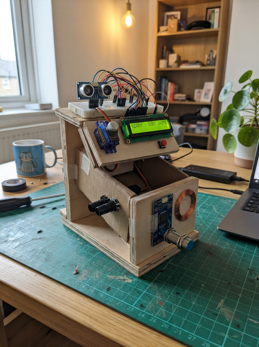
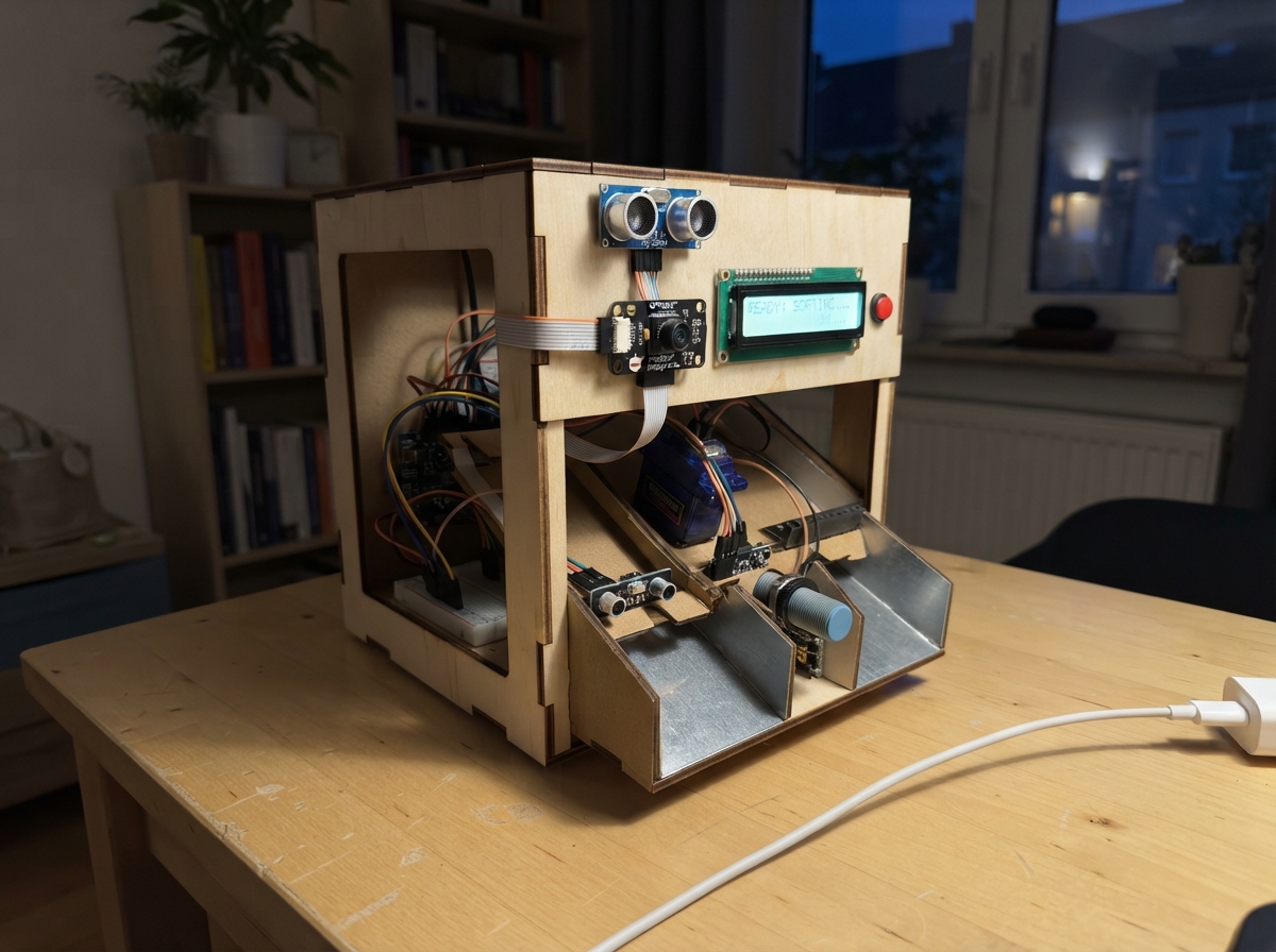
This project builds a tabletop sample sorter that uses weight and distance measurements to automatically classify objects into three categories and route them to the correct output gate. The system combines a load cell with HX711 amplifier for precise weighing, an ultrasonic distance sensor for height detection, infrared beam pairs for entry and exit sensing, and an inductive metal detector for material identification—all controlled by an Arduino with servo-driven mechanical gates and real-time feedback on a 16x2 LCD display.
The guide provides a complete wiring diagram, parts list, and step-by-step assembly instructions for mounting the rotating classification mechanism, integrating all sensors with proper electrical isolation, and programming the Arduino firmware. Builders will learn to calibrate the weight profiles for three sample groups, set safe mechanical travel limits, and troubleshoot common jams and sensor failures through the built-in diagnostic display.
Wiring diagram
Gather all the parts
Assemble it in 10 steps
1. Build a guarded tabletop sorter
Use three fixed bins and fixed receiving chutes in a 180-degree arc: blue bottle at 45 degrees, red can at 90 degrees, green paper at 135 degrees. Home is 90 degrees. The rotating tube needs an offset or angled outlet: rotating a straight tube around its own center would not change where trash falls. Put the bottom gate above a short angled outlet whose mouth sweeps the three receiving chutes. Only the tube, gate, and short outlet rotate; bins and receiving chutes stay fixed. Size for one empty dry bottle, empty aluminum can, or paper ball at a time. Use a removable loading cover and guards; this is a supervised prototype, not a public-use machine. Never put hands in the moving mechanism.
- No automatic system can guarantee safe movement without guards. No liquids, glass, batteries, sharp objects, or heavy trash.
2. Mount the weighed rotating assembly
Bolt one end of the 5kg load cell to the frame. Bolt a small floating platform to the other end with spacers, allowing the bar to flex without touching the frame. Mount the tube's bearing, rotation servo, gate and gate servo on this platform so all item weight passes through the cell. A bearing takes the tube load; do not support its weight on the servo shaft alone. Keep total assembly plus trash below 5kg, and use mechanical overload stops. Servo 1 drives tube yaw through a horn/linkage; Servo 2 travels with the tube and drives its bottom gate. Leave soft cable loops so wires neither constrain the scale nor wind up across 45–135 degrees. Do not add supports that bypass the scale.
- Gate must open freely under gravity and not pinch an object when closing. Light, empty demonstration items only. Verify servo torque with a generous margin; avoid operating near stall.
3. Fit the identification sensors
Place HC-SR04 on a stationary bracket above the home-position tube, aimed down at the item. The empty gate distance must be 10–60cm, with every sample surface at least 2cm from the transducers. A narrow guide holds bottles and cans upright at repeatable positions. Mount the LJ12A3 sensing face flush in a nonmetal wall beside the base of the sample, with no metal gate or bracket in its field. Bring the aluminum can wall within about 1mm and verify detection repeatedly; aluminum range is shorter than its advertised steel range. The sensor detects many metals, not aluminum uniquely. Only admit aluminum cans as the metal sample category. Sensor operates at home only.
4. Fit both infrared beam pairs
IR 1 uses an Adafruit 2168 transmitter and receiver across the holding region at home. IR 2 uses another pair on the rotating short outlet, below the bottom gate and above the fixed bin chutes. A passing item must fully interrupt then clear IR 2. Align beams through narrow black shrouds. Test every bottle: transparent plastic may transmit infrared, so position the beam through the cap, label or opaque base. If the exit beam misses an item, the machine deliberately awards no points. Keep hands away from the exit; an optical sensor cannot distinguish a hand from trash.
5. Connect low-voltage logic
With all supplies disconnected, use a breadboard and jumper wires for low-current signals only. Uno is powered by USB. HC-SR04 TRIG to D7 (trigger), ECHO to D6 (distance timing). IR 1 receiver OUT to D2 (item), IR 2 receiver OUT to D4 (exit); their red leads and transmitter red leads to Uno 5V, black leads to GND. LCD SDA to A4 (data), SCL to A5 (clock), VCC to 5V, GND to GND. HX711 DT to A0 (weight data), SCK to A1 (weight clock), VCC to 5V, GND to GND; use a breakout explicitly rated for 5V. Match the cell's actual excitation and signal labels to HX711 E+, E-, A+, A-; wire colors vary. Button between D5 and GND; for a four-leg button use opposite switched contacts, not two internally joined legs.
6. Isolate the 12V metal sensor
Use the exact NPN normally-open BX version, not a PNP BY version. Brown to 12V adapter positive; blue to that adapter negative. Brown also to the 2.2k 0.25W resistor, resistor to PC817 pin 1 anode, PC817 pin 2 cathode to black sensor output. On the Uno side PC817 pin 3 emitter to GND, pin 4 collector to D3. Connect the separate 10k pull-up between collector and Uno 5V. Keep the 12V adapter negative separate from Uno ground: the optocoupler bridges the two electrically isolated sides. D3 should read HIGH without metal and LOW with the sample can. Never connect brown or black directly to a Uno pin.
- A different sensor output or accidentally joining its 12V wire to logic can destroy the Uno.
7. Wire servo power and the active sounder
Use an enclosed regulated 5V 6A supply. Supply positive through the 5A inline fuse to a screw-terminal servo distribution point; supply negative to servo grounds and Uno GND. Red servo leads to fused 5V, brown to common ground, signals to D9 for rotation and D10 for gate. Add the 2200uF capacitor at these terminals, positive to servo 5V and negative stripe to ground. Never join external servo 5V to Uno 5V or route servo current through a breadboard. Use suitably rated short power wires and connectors. For the maximum-30mA 5V active piezo sounder, positive to Uno 5V, negative to transistor collector, emitter to GND, D8 through 1k to base, and 10k from base to emitter. Verify the exact transistor's B/C/E lead order from its supplier; 2N2222 and BC547 packages vary. This is an active piezo sounder, not a magnetic buzzer or passive piezo.
- Never expose mains wiring. Unplug all supplies before changing wires. A reversed electrolytic capacitor can rupture.
8. Set safe mechanical travel
First test with servo horns disconnected and the tube empty. Firmware commands gate closed 0 degrees, open 90 degrees, home 90 degrees, and blue/red/green 45/90/135 degrees. Change CLOSED, OPEN, HOME and ANGLES in the firmware to match your mechanics before fitting horns. Fit horns with power disconnected in the corresponding commanded positions. Test closed-gate alignment and collision-free travel using light samples and guards. Rotation waits 1.8 seconds before gate opening and gate waits 1 second before return; increase these constants for a slower assembly. These are timed movements, not measured position feedback. A stalled or disconnected servo cannot be detected.
9. Teach the three sample groups
First boot automatically enters calibration. To recalibrate later, hold Start during power-on for at least 2 seconds, then release. Begin with the tube empty and click once to tare; place a known 100g calibration weight on the closed gate and click. Remove the weight. For each prompted Bottle, Can, and Paper group, insert one representative sample and click; remove and replace between the three readings. Use three examples covering your allowed sample variation. Keep fingers clear while measuring. Firmware learns stable weight/height envelopes and checks inductive response; it rejects overlapping bottle/paper envelopes and asks you to reteach. After Calibration OK, remove everything and click. Profiles persist in EEPROM. Keep the tube empty whenever powering up; startup tares the complete assembly. USB serial at 115200 logs measured grams, height and metal readings for troubleshooting.
- Weight and height do not identify material universally. Only use the taught, restricted sample set. An unrelated item with the same measurements can be misclassified. If bottle/paper envelopes overlap, this mechanism is unsuitable for those samples; do not widen limits to force a decision.
10. Run and check failures
Standby shows Click to Begin and the current points. Press and release once, then insert exactly one item. Button presses while busy are discarded. Processing keeps the sounder on, identifies a unique taught group, rotates with gate closed, settles, then opens. Only an exit interruption followed by 200ms clear earns exactly two points, once, after gate closure and return home. Verify each bin and perform an unknown-item test. Unknown Trash keeps the gate closed at home: remove the sample by hand with power off if needed, then click to acknowledge when clear; another new press is required to begin. If exit is blocked or never confirms passage within 8 seconds, a latched fault awards zero points and stops motion; a released gate stays open rather than closing on a jam. Disconnect servo power before clearing; empty the assembly before restart. Points are held in RAM and reset to zero on reboot, unlike calibration. Three bins remain fixed.
- Exit passage confirms departure from the tube, not arrival in the correct bin. This design has no bin sensors, servo feedback, safety interlock, or fraud protection.
Review all connections
1. Connections between "sonar" and "Arduino"
2. Connections between "lcd" and "Arduino"
3. Connections between "scale" and "Arduino"
4. Connections between "entry" and "Arduino"
5. Connections between "exit" and "Arduino"
6. Connections between "entryTx" and "Arduino"
7. Connections between "exitTx" and "Arduino"
8. Connections between "button" and "Arduino"
9. Connections between "cell" and "Arduino"
10. Connections between "psu5" and "Arduino"
11. Connections between "fuse" and "Arduino"
12. Connections between "cap" and "Arduino"
13. Connections between "rotate" and "Arduino"
14. Connections between "gate" and "Arduino"
15. Connections between "psu12" and "Arduino"
16. Connections between "sensorR" and "Arduino"
17. Connections between "iso" and "Arduino"
18. Connections between "pull" and "Arduino"
19. Connections between "buzzer" and "Arduino"
20. Connections between "driver" and "Arduino"
21. Connections between "baseR" and "Arduino"
22. Connections between "basePull" and "Arduino"
Deploy the firmware
#include <Arduino.h>
#include <Wire.h>
#include <Servo.h>
#include <EEPROM.h>
#include <hd44780.h>
#include <hd44780ioClass/hd44780_I2Cexp.h>
#include <math.h>
// Controlled sample classifier, not chemical material identification.
const byte ENTRY=2,METAL=3,EXIT=4,BUTTON=5,ECHO=6,TRIG=7,BUZZER=8;
const byte ROTATE=9,GATE=10,DT=A0,HX_CLOCK=A1;
const byte HOME=90,CLOSED=0,OPEN=90;
const byte ANGLES[]={45,90,135};
const unsigned long ROTATE_MS=1800,GATE_MS=1000,EXIT_MS=8000;
Servo tube,gate;
hd44780_I2Cexp lcd;
struct Profile { float w0,w1,h0,h1; };
struct Calibration { uint32_t magic; float factor,emptyDistance; Profile p[3]; uint16_t check; } cal;
const uint32_t MAGIC=0x57535433UL;
long zeroRaw=0;
uint32_t points=0,entered=0,lastButtonChange=0;
byte buttonRaw=HIGH,buttonStable=HIGH;
bool calibrated=false,seenExit=false,exitCleared=false;
uint32_t clearSince=0;
int kind=-1;
enum State {STANDBY,WAIT_ITEM,DETECTED,IDENTIFIED,ROTATING,RELEASING,CLOSING,RETURNING,SUCCESS,TOTAL,UNKNOWN,JAM,CAL_EMPTY,CAL_WEIGHT,CAL_SAMPLE,CAL_DONE};
State state=STANDBY;
byte teachClass=0,teachRepeat=0;
void screen(const __FlashStringHelper *a,const __FlashStringHelper *b) {
 lcd.clear(); lcd.setCursor(0,0);lcd.print(a);lcd.setCursor(0,1);lcd.print(b);
}
void enter(State s){state=s;entered=millis();}
void standby(){digitalWrite(BUZZER,LOW);enter(STANDBY);lcd.clear();lcd.print(F("Click to Begin"));lcd.setCursor(0,1);lcd.print(F("Points: "));lcd.print(points);}
bool press(){
 byte r=digitalRead(BUTTON);
 if(r!=buttonRaw){buttonRaw=r;lastButtonChange=millis();}
 if(r!=buttonStable && millis()-lastButtonChange>=35){buttonStable=r;return r==LOW;}
 return false;
}
bool raw(long &v){
 uint32_t start=millis();while(digitalRead(DT)){if(millis()-start>250)return false;}
 unsigned long x=0;
 // Keep HX_CLOCK high under 60us even when the servo interrupt fires.
 for(byte i=0;i<24;i++){noInterrupts();digitalWrite(HX_CLOCK,HIGH);delayMicroseconds(1);x=(x<<1)|digitalRead(DT);digitalWrite(HX_CLOCK,LOW);interrupts();delayMicroseconds(1);}
 noInterrupts();digitalWrite(HX_CLOCK,HIGH);delayMicroseconds(1);digitalWrite(HX_CLOCK,LOW);interrupts(); // 25th clock selects A gain 128
 if(x&0x800000UL)x|=0xFF000000UL;v=(long)x;return true;
}
bool average(long &v){long x;int64_t sum=0;for(byte i=0;i<10;i++){if(!raw(x))return false;sum+=x;}v=(long)(sum/10);return true;}
float distance(){
 digitalWrite(TRIG,LOW);delayMicroseconds(3);digitalWrite(TRIG,HIGH);delayMicroseconds(10);digitalWrite(TRIG,LOW);
 unsigned long t=pulseIn(ECHO,HIGH,25000UL);return t?t/58.0f:-1;
}
bool measure(float &w,float &h,bool &metal){
 float wl=1e9,wh=-1e9,dl=1e9,dh=-1e9,ws=0,ds=0;byte metals=0;
 for(byte i=0;i<10;i++){
  long x;if(!raw(x))return false;float a=(x-zeroRaw)/cal.factor;float d=distance();if(d<2 || d>60)return false;
  wl=min(wl,a);wh=max(wh,a);dl=min(dl,d);dh=max(dh,d);ws+=a;ds+=d;
  if(digitalRead(METAL)==LOW)metals++;delay(65);
 }
 w=ws/10;h=(cal.emptyDistance-ds/10)*10;metal=metals>=9;
 Serial.print(F("grams="));Serial.print(w);Serial.print(F(" height_mm="));Serial.print(h);Serial.print(F(" metal_samples="));Serial.println(metals);
 return wh-wl<=max(1.0f,fabs(w)*0.08f) && dh-dl<=1.2f && (metals<=1 || metals>=9) && w>0.5 && h>5;
}
uint16_t checksum(){uint16_t s=0;byte *p=(byte*)&cal;for(unsigned i=0;i<sizeof(cal)-sizeof(cal.check);i++)s=(s*31)^p[i];return s;}
void unknown(){digitalWrite(BUZZER,LOW);enter(UNKNOWN);screen(F("Unknown Trash"),F("Remove; click"));}
void jam(){digitalWrite(BUZZER,LOW);enter(JAM);screen(F("Jam / Exit Fault"),F("Power off; clear"));}
void samplePrompt(){
 lcd.clear();lcd.print(teachClass==0?F("Bottle sample"):teachClass==1?F("Can sample"):F("Paper sample"));lcd.setCursor(0,1);lcd.print(teachRepeat+1);lcd.print(F("/3 Place; click"));
}
void setup(){
 pinMode(ENTRY,INPUT_PULLUP);pinMode(EXIT,INPUT_PULLUP);pinMode(METAL,INPUT_PULLUP);pinMode(BUTTON,INPUT_PULLUP);
 pinMode(BUZZER,OUTPUT);digitalWrite(BUZZER,LOW);pinMode(TRIG,OUTPUT);pinMode(ECHO,INPUT);pinMode(DT,INPUT);pinMode(HX_CLOCK,OUTPUT);digitalWrite(HX_CLOCK,LOW);
 Serial.begin(115200);Wire.begin();if(lcd.begin(16,2)){while(true){delay(100);}}
 // Set closed before attaching. Mechanical stops must be calibrated unloaded.
 gate.write(CLOSED);gate.attach(GATE);delay(GATE_MS);tube.write(HOME);tube.attach(ROTATE);delay(ROTATE_MS);
 EEPROM.get(0,cal);calibrated=cal.magic==MAGIC && cal.check==checksum() && fabs(cal.factor)>0.01f;
 bool teach=digitalRead(BUTTON)==LOW;
 if(teach){delay(2000);teach=digitalRead(BUTTON)==LOW;}
 buttonRaw=buttonStable=digitalRead(BUTTON);lastButtonChange=millis();
 if(teach || !calibrated){cal.magic=0;cal.factor=1;enter(CAL_EMPTY);screen(F("Calibration"),F("Empty; click"));return;}
 screen(F("Keep tube empty"),F("Taring scale..."));delay(1500);
 if(!average(zeroRaw) || digitalRead(ENTRY)==LOW || digitalRead(EXIT)==LOW){unknown();return;}
 standby();
}
void loop(){
 bool clicked=press();uint32_t now=millis();
 if(state==CAL_EMPTY && clicked){
  if(digitalRead(ENTRY)==LOW || digitalRead(EXIT)==LOW)return;
  if(!average(zeroRaw)){screen(F("Scale fault"),F("Check HX711"));return;}
  float d=distance();if(d<10 || d>60){screen(F("Sonar fault"),F("Check placement"));return;}
  cal.emptyDistance=d;enter(CAL_WEIGHT);screen(F("Place 100 grams"),F("Then click"));return;
 }
 if(state==CAL_WEIGHT && clicked){long x;if(!average(x) || labs(x-zeroRaw)<100){screen(F("Scale fault"),F("Retry 100 grams"));return;}cal.factor=(x-zeroRaw)/100.0f;teachClass=0;teachRepeat=0;enter(CAL_SAMPLE);samplePrompt();return;}
 if(state==CAL_SAMPLE && clicked){
  float w,h;bool m;if(!measure(w,h,m) || m!=(teachClass==1)){screen(F("Unstable / Metal"),F("Fix sample;click"));return;}
  Profile &p=cal.p[teachClass];float wm=max(0.8f,w*0.12f),hm=10;
  if(!teachRepeat){p={w-wm,w+wm,h-hm,h+hm};}else{p.w0=min(p.w0,w-wm);p.w1=max(p.w1,w+wm);p.h0=min(p.h0,h-hm);p.h1=max(p.h1,h+hm);}
  teachRepeat++;
  if(teachRepeat==3){teachRepeat=0;teachClass++;}
  if(teachClass<3){samplePrompt();return;}
  Profile a=cal.p[0],b=cal.p[2];
  if(a.w0<=b.w1 && b.w0<=a.w1 && a.h0<=b.h1 && b.h0<=a.h1){enter(CAL_EMPTY);screen(F("Samples overlap"),F("Empty; reteach"));return;}
  cal.magic=MAGIC;cal.check=checksum();EEPROM.put(0,cal);calibrated=true;enter(CAL_DONE);screen(F("Calibration OK"),F("Empty; click"));return;
 }
 if(state==CAL_DONE && clicked){if(digitalRead(ENTRY)==LOW || digitalRead(EXIT)==LOW)return;if(!average(zeroRaw))return;standby();return;}
 if(state==STANDBY && clicked){
  if(!calibrated || digitalRead(ENTRY)==LOW || digitalRead(EXIT)==LOW){unknown();return;}
  long x;if(!average(x) || fabs((x-zeroRaw)/cal.factor)>1.5f){unknown();return;}
  enter(WAIT_ITEM);screen(F("Insert Trash"),F("Ready to Sort"));return;
 }
 if(state==WAIT_ITEM){
  if(digitalRead(ENTRY)==LOW){digitalWrite(BUZZER,HIGH);enter(DETECTED);screen(F("Trash Detected"),F("On Processing"));}
  else if(now-entered>60000)standby();return;
 }
 if(state==DETECTED && now-entered>=1200){
  float w,h;bool m;if(!measure(w,h,m)){unknown();return;}
  int matches=0;kind=-1;
  for(byte i=0;i<3;i++){Profile p=cal.p[i];if(m==(i==1) && w>=p.w0 && w<=p.w1 && h>=p.h0 && h<=p.h1){matches++;kind=i;}}
  if(matches!=1){unknown();return;}
  enter(IDENTIFIED);screen(F("Trash Identified"),kind==0?F("Plastic Bottle"):kind==1?F("Aluminum Can"):F("Crumpled Paper"));return;
 }
 if(state==IDENTIFIED && now-entered>=1500){
  if(digitalRead(EXIT)==LOW){unknown();return;}
  gate.write(CLOSED);tube.write(ANGLES[kind]);enter(ROTATING);screen(F("Sorting Trash"),F("Please Wait..."));return;
 }
 if(state==ROTATING && now-entered>=ROTATE_MS){
  if(digitalRead(EXIT)==LOW){jam();return;}
  seenExit=false;exitCleared=false;clearSince=0;gate.write(OPEN);enter(RELEASING);return;
 }
 if(state==RELEASING){
  if(digitalRead(EXIT)==LOW){seenExit=true;exitCleared=false;clearSince=0;}else if(seenExit){if(!clearSince)clearSince=now;if(now-clearSince>=200)exitCleared=true;}
  if(exitCleared && now-entered>=GATE_MS){gate.write(CLOSED);enter(CLOSING);return;}
  if(now-entered>=EXIT_MS){jam();return;}
 }
 if(state==CLOSING && now-entered>=GATE_MS){tube.write(HOME);enter(RETURNING);return;}
 if(state==RETURNING && now-entered>=ROTATE_MS){
  digitalWrite(BUZZER,LOW);if(points<=4294967293UL)points+=2;else{jam();return;}
  enter(SUCCESS);screen(kind==0?F("Bottle Sorted!"):kind==1?F("Can Sorted!"):F("Paper Sorted!"),F("+2 Points"));return;
 }
 if(state==SUCCESS && now-entered>=1800){enter(TOTAL);lcd.clear();lcd.print(F("Sorting Success"));lcd.setCursor(0,1);lcd.print(F("Total: "));lcd.print(points);lcd.print(F(" Points"));return;}
 if(state==TOTAL && now-entered>=2200){standby();return;}
 if(state==UNKNOWN && clicked){
  if(!calibrated){enter(CAL_EMPTY);screen(F("Calibration"),F("Empty; click"));return;}
  long x;if(digitalRead(ENTRY)==HIGH && digitalRead(EXIT)==HIGH && average(x) && fabs((x-zeroRaw)/cal.factor)<1.5f)standby();
 }
 // JAM is latched. Never rotate with a potentially trapped item or close on it.
}
Remix this project
Make it yours in one click
Open a full copy of this project in your own Schematik workspace, diagram, code, parts, and assembly steps included. Swap the sensor, add features, or redesign the whole thing with AI. The author's original stays untouched.