Community project
Flight Radar Display
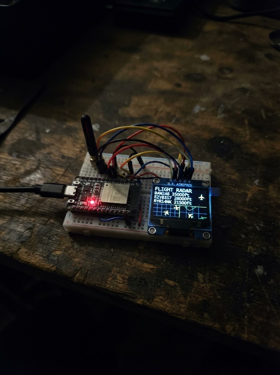
This project turns an M5Dial into a flight radar display that visualizes aircraft tracks with bearing, range, altitude, and speed information. The display renders a classic radar scope with concentric range rings and a rotating sweep, plotting nearby aircraft as colored symbols with their callsigns and flight data.
The guide provides a complete firmware implementation for the ESP32-based M5Dial, including the wiring setup (power only), parts list, and step-by-step assembly instructions. The code demonstrates radar rendering with polar-to-cartesian coordinate conversion; users can extend it by connecting to a real flight-data API to replace the sample aircraft tracks with live ADS-B or aviation data.
Wiring diagram
Assemble it in 2 steps
1. Use the M5Dial as supplied
No external electronic parts are required. The round screen, rotary encoder, and buzzer used by this project are already built into the M5Dial.
- Keep the protective film on the display only if it does not obscure viewing; remove it for the clearest radar image.
- Do not open the enclosure or connect wires to the internal display pins; the M5Dial library controls its built-in hardware.
2. Power the M5Dial
Connect the M5Dial to a suitable USB power source using its USB-C connector. The board is powered through its normal USB port.
- A standard USB power source is sufficient for this display-only project.
- Use a sound USB-C cable and avoid loose connections while the device is operating.
Deploy the firmware
#include <Arduino.h>
#include <M5Dial.h>
#include <math.h>

// Demonstration radar: replace these sample tracks with data returned by
// a flight-data service when network credentials and an API are selected.
struct Track {
  const char *callsign;
  float bearing;
  float rangeNm;
  float speedKt;
  int altitudeFt;
  float turnRate;
};

float radiansFromBearing(float bearing);
void polarPoint(float bearing, float radius, int &x, int &y);
void drawStaticRadar();
void drawAircraft(const Track &track);
void renderFrame();

constexpr int SCREEN_W = 240;
constexpr int SCREEN_H = 240;
constexpr int CX = 120;
constexpr int CY = 120;
constexpr int RADAR_R = 92;
constexpr uint16_t BG = 0x0000;
constexpr uint16_t GRID = 0x03E0;
constexpr uint16_t DIM_GRID = 0x01A0;
constexpr uint16_t AIRCRAFT = 0xFFE0;
constexpr uint16_t TEXT = 0xFFFF;
constexpr uint16_t ALERT = 0xF800;
constexpr unsigned long FRAME_MS = 50;

Track tracks[] = {
  {"SWA482", 32.0f, 10.5f, 438.0f, 32100, 0.18f},
  {"DAL921", 148.0f, 23.0f, 465.0f, 28700, -0.12f},
  {"AAL76", 258.0f, 34.0f, 410.0f, 35600, 0.08f},
  {"UAL120", 312.0f, 42.0f, 492.0f, 30200, -0.16f}
};
constexpr size_t TRACK_COUNT = sizeof(tracks) / sizeof(tracks[0]);

float sweepBearing = 0.0f;
unsigned long lastFrame = 0;

float radiansFromBearing(float bearing) {
  return (bearing - 90.0f) * DEG_TO_RAD;
}

void polarPoint(float bearing, float radius, int &x, int &y) {
  const float angle = radiansFromBearing(bearing);
  x = CX + static_cast<int>(lroundf(cosf(angle) * radius));
  y = CY + static_cast<int>(lroundf(sinf(angle) * radius));
}

void drawStaticRadar() {
  M5Dial.Display.fillScreen(BG);
  M5Dial.Display.drawCircle(CX, CY, RADAR_R, GRID);
  M5Dial.Display.drawCircle(CX, CY, RADAR_R * 2 / 3, DIM_GRID);
  M5Dial.Display.drawCircle(CX, CY, RADAR_R / 3, DIM_GRID);
  M5Dial.Display.drawLine(CX - RADAR_R, CY, CX + RADAR_R, CY, DIM_GRID);
  M5Dial.Display.drawLine(CX, CY - RADAR_R, CX, CY + RADAR_R, DIM_GRID);
  M5Dial.Display.fillCircle(CX, CY, 3, GRID);

  M5Dial.Display.setTextColor(TEXT, BG);
  M5Dial.Display.setTextSize(1);
  M5Dial.Display.setTextDatum(middle_center);
  M5Dial.Display.drawString("FLIGHT RADAR", CX, 10);
  M5Dial.Display.drawString("N", CX, 23);
  M5Dial.Display.drawString("50 NM", CX, 218);
  M5Dial.Display.setTextDatum(top_left);
}

void drawAircraft(const Track &track) {
  const float radius = constrain(track.rangeNm / 50.0f, 0.0f, 1.0f) * RADAR_R;
  int x, y;
  polarPoint(track.bearing, radius, x, y);

  const uint16_t colour = track.rangeNm < 15.0f ? ALERT : AIRCRAFT;
  M5Dial.Display.fillCircle(x, y, 3, colour);
  M5Dial.Display.drawLine(
      x, y,
      x + static_cast<int>(cosf(radiansFromBearing(track.bearing)) * 8),
      y + static_cast<int>(sinf(radiansFromBearing(track.bearing)) * 8), colour);

  M5Dial.Display.setTextColor(colour, BG);
  M5Dial.Display.setTextSize(1);
  M5Dial.Display.setCursor(x + 6, y - 8);
  M5Dial.Display.print(track.callsign);
}

void renderFrame() {
  drawStaticRadar();
  for (size_t i = 0; i < TRACK_COUNT; ++i) {
    tracks[i].bearing += tracks[i].turnRate;
    if (tracks[i].bearing >= 360.0f) tracks[i].bearing -= 360.0f;
    if (tracks[i].bearing < 0.0f) tracks[i].bearing += 360.0f;
    drawAircraft(tracks[i]);
  }

  int sweepX, sweepY;
  polarPoint(sweepBearing, RADAR_R, sweepX, sweepY);
  M5Dial.Display.drawLine(CX, CY, sweepX, sweepY, AIRCRAFT);
  sweepBearing += 2.2f;
  if (sweepBearing >= 360.0f) sweepBearing -= 360.0f;
}

void setup() {
  auto cfg = M5.config();
  M5Dial.begin(cfg, true, false);
  M5Dial.Display.setRotation(0);
  M5Dial.Display.setTextWrap(false);
  renderFrame();
}

void loop() {
  M5Dial.update();
  const unsigned long now = millis();
  if (now - lastFrame >= FRAME_MS) {
    lastFrame = now;
    renderFrame();
  }
}
Remix this project
Make it yours in one click
Open a full copy of this project in your own Schematik workspace — diagram, code, parts, and assembly steps included. Swap the sensor, add features, or redesign the whole thing with AI. The author's original stays untouched.