Community project
Fridge Scale Smart Clip
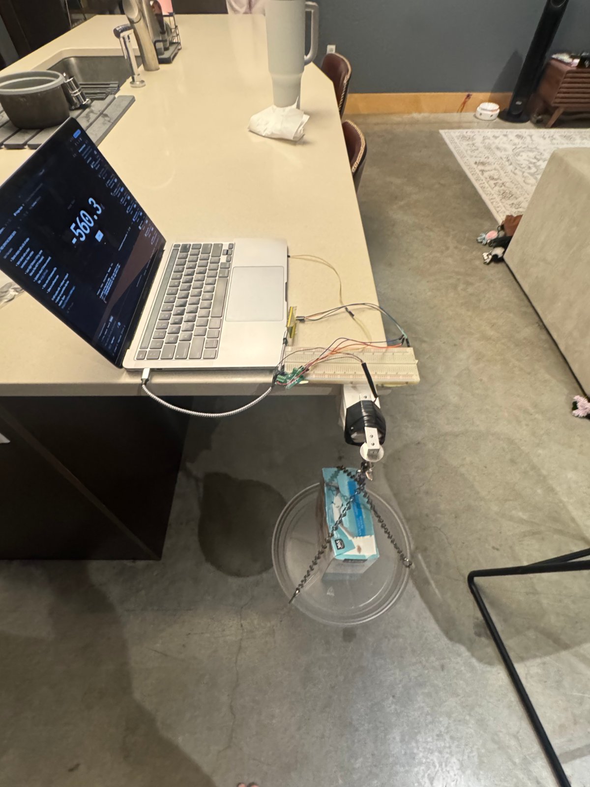
This project turns a Raspberry Pi Pico into a smart weight monitor for a refrigerator by connecting a 10 kg hanging load cell through an HX711 amplifier. The load cell clips onto shelves or hooks, allowing real-time tracking of food weight and inventory changes. The guide includes a wiring diagram, complete parts list, and firmware code that reads raw sensor data and averages multiple samples for stable measurements.
Builders will learn how to solder the HX711 terminal block, mechanically secure the hanging sensor, and wire four connections to the Pico's GPIO pins. The provided firmware demonstrates how to communicate with the HX711 using bit-banged SPI protocol, with calibration and weight calculation ready for customization based on your specific setup.
Wiring diagram

Gather all the parts
Assemble it in 3 steps
1. Solder the terminal onto the HX711
Keep the Pico unplugged. Put the four-position screw terminal through the HX711 holes marked E+, E−, A+, and A−, with the screw openings facing outward. Solder its four pins on the back of the HX711 board, starting at about 300°C. Let the board cool and make sure neighboring solder joints do not touch.
- The terminal is part of the HX711 board after soldering; it is not a separate board.
- A small, smooth solder joint is enough.
- Keep power disconnected while soldering.
- Solder joining two neighboring pins can stop the sensor from working.
2. Clamp the hanging sensor into the terminal
Support the sensor by its metal ring and hook, never by its thin wires. Identify each sensor wire from the supplier information or its markings, then clamp E+ into HX711 E+, E− into HX711 E−, A+ into HX711 A+, and A− into HX711 A−. Leave a small loose cable loop so a pull on the cable does not pull on the terminal.
- The wire-color mapping is pending verification; use the E+/E−/A+/A− identification, not an assumed color order.
- Gently tug each wire after tightening its screw.
- Do not let bare wire ends touch each other; that can cause incorrect readings.
- Never hang weight from the thin sensor wires.
3. Make the four Pico connections
Use jumper wires on the breadboard only between the HX711 and Pico: HX711 VCC → Pico 3V3 (power), HX711 GND → Pico GND (ground), HX711 DT/DOUT → Pico GP16 (data), and HX711 SCK/CLK → Pico GP17 (clock). Connect the Pico to the computer with USB. Keep the Pico and HX711 away from the possible path of a falling test weight.
- The breadboard is only a holder for the four thicker jumper connections; the sensor wires do not go through it.
- The Pico firmware uses MicroPython and initially prints uncalibrated readings.
- Do not load the hanging sensor above 10 kg or stand below the test weight.
- The planned wiring has not yet been validated with the new sensor.
Review all connections
1. Connections between "hx711_1" and "Raspberry Pi Pico"
2. Connections between "hx711_terminal_block_1" and "Raspberry Pi Pico"
3. Connections between "load_cell_10kg_hanging_1" and "Raspberry Pi Pico"
Deploy the firmware
#include <Arduino.h>

// Planned first test for the 10 kg hanging load cell: print uncalibrated raw changes.

// Forward declarations
bool readRaw(long &value);
bool averageRaw(uint8_t count, long &average);

constexpr uint8_t HX711_DT_PIN = 16;
constexpr uint8_t HX711_SCK_PIN = 17;
constexpr uint8_t SAMPLES_PER_READING = 10;
constexpr unsigned long SAMPLE_INTERVAL_MS = 500;
constexpr unsigned long READY_TIMEOUT_MS = 2000;

bool readRaw(long &value) {
  unsigned long start = millis();
  while (digitalRead(HX711_DT_PIN) == HIGH) {
    if (millis() - start >= READY_TIMEOUT_MS) {
      return false;
    }
    delay(1);
  }

  uint32_t raw = 0;
  noInterrupts();
  for (uint8_t bit = 0; bit < 24; ++bit) {
    digitalWrite(HX711_SCK_PIN, HIGH);
    raw = (raw << 1) | static_cast<uint32_t>(digitalRead(HX711_DT_PIN));
    digitalWrite(HX711_SCK_PIN, LOW);
  }
  // One extra pulse selects gain 128 for the following conversion.
  digitalWrite(HX711_SCK_PIN, HIGH);
  digitalWrite(HX711_SCK_PIN, LOW);
  interrupts();

  if (raw & 0x800000UL) {
    raw |= 0xFF000000UL;
  }
  value = static_cast<long>(static_cast<int32_t>(raw));
  return true;
}

bool averageRaw(uint8_t count, long &average) {
  int64_t total = 0;
  for (uint8_t i = 0; i < count; ++i) {
    long reading = 0;
    if (!readRaw(reading)) {
      return false;
    }
    total += reading;
  }
  average = static_cast<long>(total / count);
  return true;
}

void setup() {
  Serial.begin(115200);
  pinMode(HX711_DT_PIN, INPUT);
  pinMode(HX711_SCK_PIN, OUTPUT);
  digitalWrite(HX711_SCK_PIN, LOW);

  Serial.println("Hanging scale planned test");
  Serial.println("Leave the hook empty and still while zero is measured.");
  delay(1000);
}

void loop() {
  static bool zeroCaptured = false;
  static long zeroOffset = 0;

  long reading = 0;
  if (!averageRaw(SAMPLES_PER_READING, reading)) {
    Serial.println("HX711 not ready: check VCC, GND, DT, and SCK wiring.");
    delay(SAMPLE_INTERVAL_MS);
    return;
  }

  if (!zeroCaptured) {
    zeroOffset = reading;
    zeroCaptured = true;
    Serial.println("Empty-hook zero captured. Raw change readings follow.");
  } else {
    Serial.println(reading - zeroOffset);
  }
  delay(SAMPLE_INTERVAL_MS);
}
Remix this project
Make it yours in one click
Open a full copy of this project in your own Schematik workspace — diagram, code, parts, and assembly steps included. Swap the sensor, add features, or redesign the whole thing with AI. The author's original stays untouched.
Related projects
Tiny Robot AI Assistant
Raspberry Pi Pico · September 13, 2026Shaikh Tajmul haque
Tiny Spider Robot
Raspberry Pi Pico · September 13, 2026Shaikh Tajmul haque
Portable ESP32 Laptop
Raspberry Pi Pico · September 12, 2026Sven Celikovic