Community project
GPS Speedometer
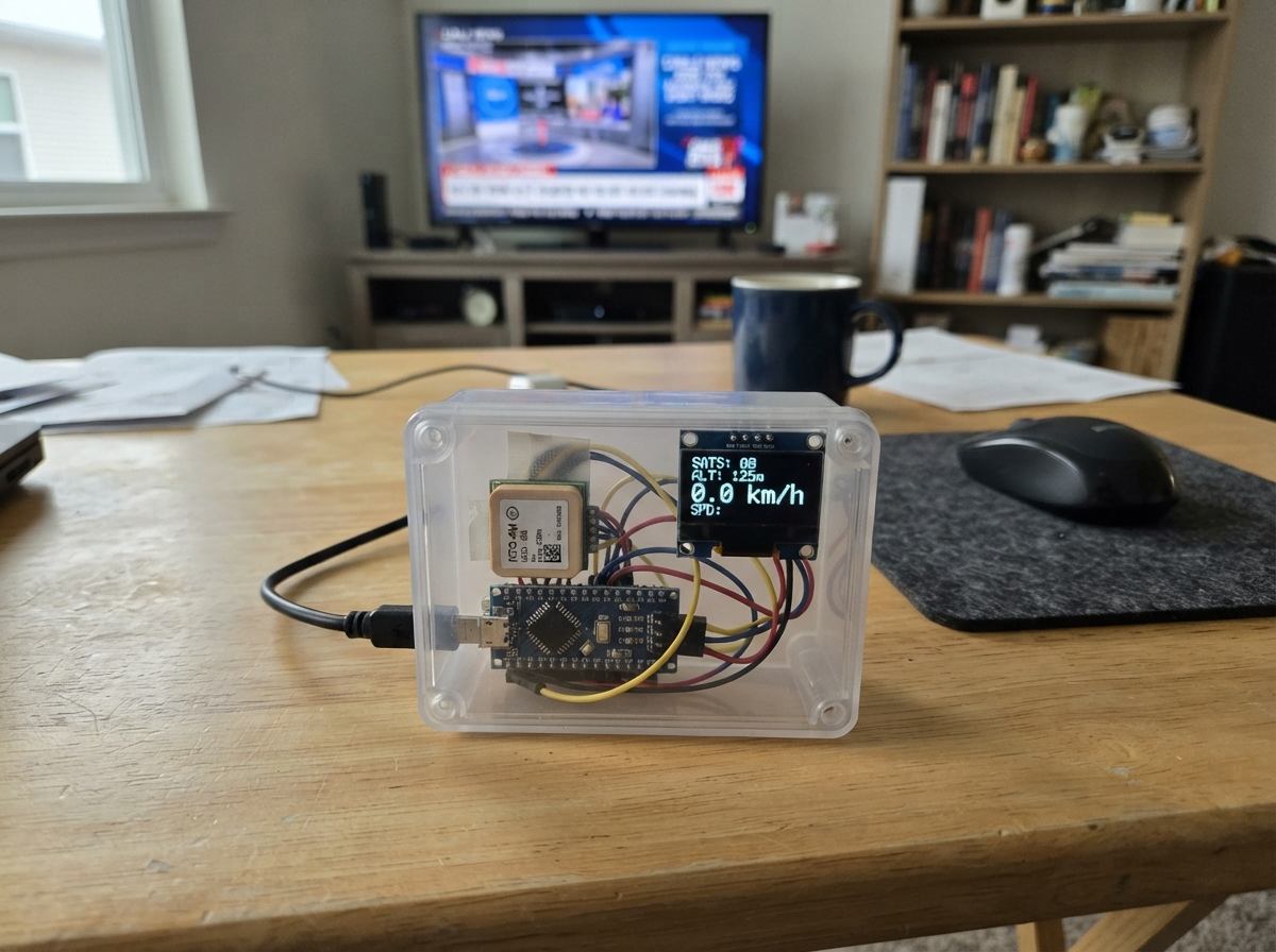
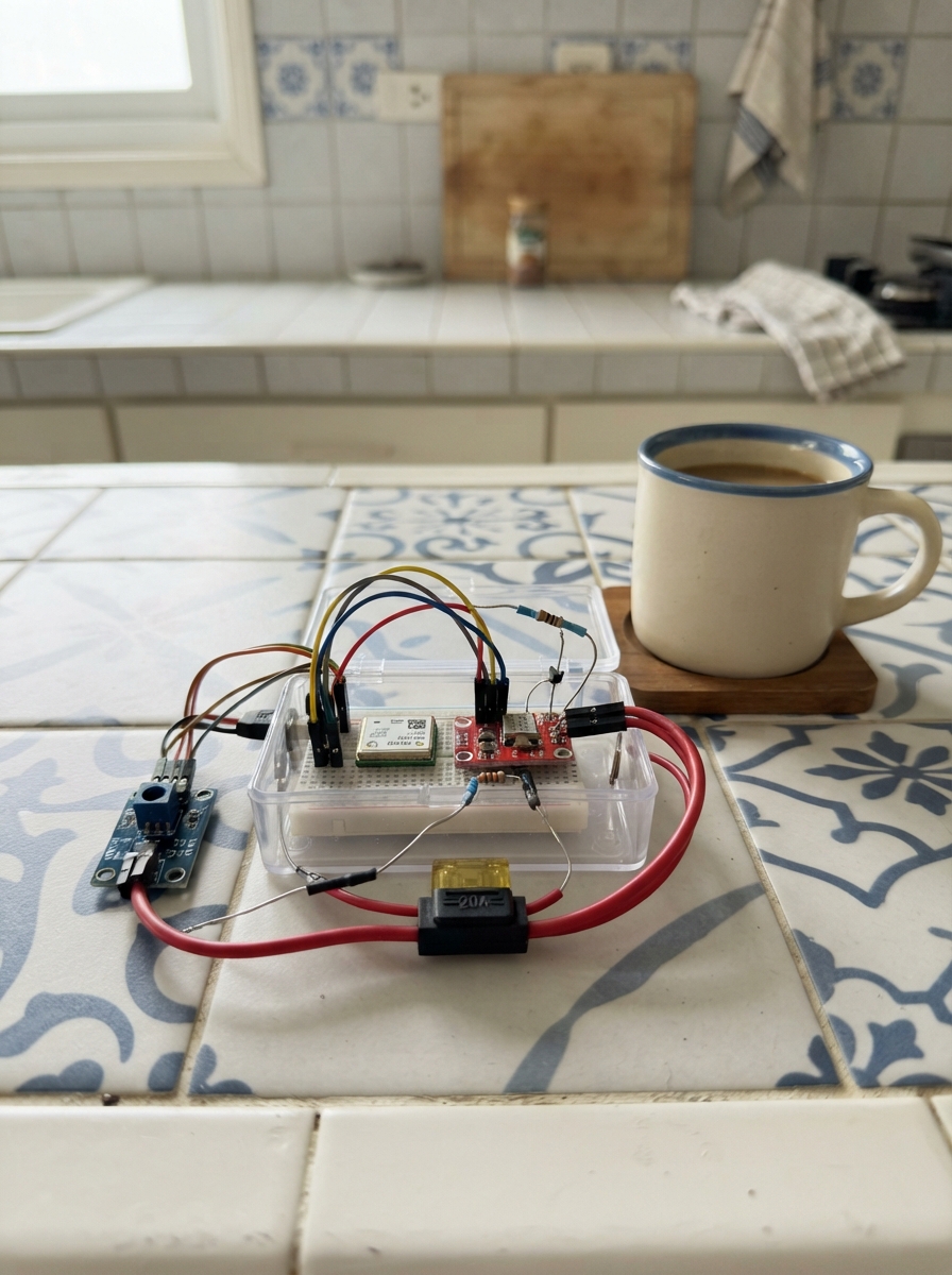
This GPS speedometer reads real-time velocity data from a NEO-6M GPS module and displays it on a TFT screen. The ESP32 processes satellite signals to calculate speed and tracks the maximum velocity reached during operation.
The guide includes a complete wiring diagram showing how to connect the GPS module's power and serial data lines to the ESP32, a full parts list, and ready-to-upload firmware that handles GPS parsing, display rendering, and speed calculations. Assembly takes just a few minutes, and once powered up, the device will acquire a satellite lock and begin showing live speed readings.
Wiring diagram

Gather all the parts
Assemble it in 4 steps
1. Place the GPS receiver
Put the NEO-6M GPS module where its small square antenna faces upward and is not covered by metal. For the first test, place it near a window or outdoors so it can see the sky.
- The first satellite lock can take several minutes, especially after the module has been stored without power.
- Do not put the antenna directly under the ESP32 board or a metal case; blocked sky view prevents a speed reading.
2. Connect GPS power
With the ESP32 unplugged, connect the GPS VCC pin to the board 3V3 pin (power). Connect GPS GND to a board GND pin (ground).
- Use short jumper wires and make sure the labels on the GPS module match the labels you connect.
- Do not connect GPS VCC to 5V unless your exact GPS breakout is clearly marked as accepting 5V; the design uses the safe 3.3V connection. Swapped VCC and GND can damage the GPS module.
3. Connect the two data wires
Connect GPS TX to ESP32 GPIO3 / RX0 (data). Connect GPS RX to ESP32 GPIO1 / TX0 (data). Leave the GPS PPS pin unconnected.
- TX and RX cross over: the GPS pin marked TX goes to the board pin marked RX0, and GPS RX goes to TX0.
- Keep these two wires clear of VCC and GND. A loose TX wire will leave the display showing SEARCHING.
4. Power up and get a satellite lock
Check every connection once more, then plug the ESP32 board into USB. Put the antenna where it can see open sky; the screen changes from SEARCHING to LOCKED when the GPS receiver has enough satellites.
- Walk or ride slowly in an open area after it says LOCKED; the large number should then show your speed in km/h.
- Do not use the displayed speed as a safety-critical instrument while driving; use the vehicle's approved speedometer and obey local laws.
Review all connections
1. Connections between "gps_neo6m" and "ESP32"
Deploy the firmware
#include <Arduino.h>
#include <TinyGPS++.h>
#include <Arduino_GFX_Library.h>


// Forward declarations
void drawStaticScreen();
void drawSpeed(float speed);
void drawStatus(bool fixed);
void drawTopSpeed();

constexpr int GPS_RX_PIN = 3;  // GPS TX connects here
constexpr int GPS_TX_PIN = 1;  // GPS RX connects here
constexpr uint32_t GPS_BAUD = 9600;

HardwareSerial gpsSerial(2);
TinyGPSPlus gps;

Arduino_ESP32SPI tftBus(2, 15, 14, 13, GFX_NOT_DEFINED);
Arduino_ILI9341 display(&tftBus, GFX_NOT_DEFINED, 0, false, 240, 320);

float shownSpeed = -1.0f;
float topSpeed = 0.0f;
bool shownFix = false;
uint32_t lastDataMs = 0;

void drawStaticScreen() {
  display.fillScreen(BLACK);
  display.setTextColor(CYAN);
  display.setTextSize(2);
  display.setCursor(44, 22);
  display.print("SPEEDOMETER");

  display.drawRoundRect(12, 58, 216, 142, 12, DARKCYAN);
  display.setTextColor(WHITE);
  display.setTextSize(2);
  display.setCursor(91, 168);
  display.print("km/h");

  display.drawFastHLine(20, 205, 200, DARKGREY);
  display.setTextColor(LIGHTGREY);
  display.setTextSize(2);
  display.setCursor(24, 220);
  display.print("TOP:");
  display.setCursor(24, 250);
  display.print("GPS:");

}

void drawSpeed(float speed) {
  display.fillRoundRect(18, 64, 204, 130, 8, BLACK);
  display.setTextColor(speed < 1.0f ? ORANGE : GREEN);
  display.setTextSize(7);
  char speedText[10];
  snprintf(speedText, sizeof(speedText), "%3.0f", speed);
  int16_t x1, y1;
  uint16_t w, h;
  display.getTextBounds(speedText, 0, 0, &x1, &y1, &w, &h);
  display.setCursor((240 - w) / 2, 104);
  display.print(speedText);
}

void drawStatus(bool fixed) {
  display.fillRect(82, 246, 140, 20, BLACK);
  display.setTextSize(2);
  display.setTextColor(fixed ? GREEN : RED);
  display.setCursor(82, 250);
  display.print(fixed ? "LOCKED" : "SEARCHING");
}

void drawTopSpeed() {
  display.fillRect(82, 216, 130, 22, BLACK);
  display.setTextColor(YELLOW);
  display.setTextSize(2);
  display.setCursor(82, 220);
  display.printf("%.1f km/h", topSpeed);
}

void setup() {
  display.begin();
  display.setRotation(0);
  drawStaticScreen();
  drawSpeed(0.0f);
  drawTopSpeed();
  drawStatus(false);
  gpsSerial.begin(GPS_BAUD, SERIAL_8N1, GPS_RX_PIN, GPS_TX_PIN);
}

void loop() {
  while (gpsSerial.available() > 0) {
    gps.encode(gpsSerial.read());
  }

  const bool hasRecentFix = gps.location.isValid() && gps.location.age() < 3000;
  if (hasRecentFix != shownFix) {
    shownFix = hasRecentFix;
    drawStatus(shownFix);
  }

  if (gps.speed.isUpdated()) {
    lastDataMs = millis();
    float speedKmh = gps.speed.kmph();
    if (speedKmh < 0.5f) speedKmh = 0.0f;
    if (speedKmh > topSpeed) {
      topSpeed = speedKmh;
      drawTopSpeed();
    }
    if (fabs(speedKmh - shownSpeed) >= 0.5f) {
      shownSpeed = speedKmh;
      drawSpeed(speedKmh);
    }
  }

  if (millis() - lastDataMs > 3500 && shownSpeed != 0.0f) {
    shownSpeed = 0.0f;
    drawSpeed(0.0f);
  }

  delay(5);
}
Remix this project
Make it yours in one click
Open a full copy of this project in your own Schematik workspace — diagram, code, parts, and assembly steps included. Swap the sensor, add features, or redesign the whole thing with AI. The author's original stays untouched.