Community project
Ik Wil Een Flipper Zero Maken Met Esp
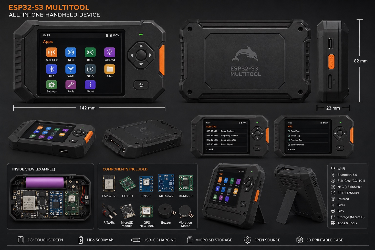
Build a Flipper Zero-inspired multi-tool on the ESP32 that combines NFC reading, infrared control, sub-GHz radio monitoring, and WiFi scanning into a single handheld device. This project brings together affordable off-the-shelf modules—an SSD1306 OLED display, PN532 NFC reader, CC1101 sub-GHz transceiver, IR transmitter and receiver, and navigation buttons—to create a versatile RF exploration and control platform.
This guide provides a complete wiring diagram, parts list, and step-by-step assembly instructions to integrate all modules onto a breadboard or custom PCB. The included Arduino firmware handles I2C communication with the display and NFC module, manages IR send/receive via the 38 kHz protocol, interfaces with the CC1101 radio, and presents a menu-driven interface for navigating between tools. Builders will learn practical techniques for power distribution, multi-protocol integration, and safe RF hardware testing.
Wiring diagram

Gather all the parts
Assemble it in 7 steps
1. Voedingsrails voorbereiden
Gebruik de USB-poort van de ESP32 DevKit v1 als voeding tijdens het bouwen. Verbind alle GND-pinnen van de modules met GND van de ESP32. Gebruik uitsluitend de 3V3-pen voor OLED, PN532, CC1101 en IR-ontvanger.
- Houd alle signaaldraden kort.
- De ESP32 GPIO's zijn 3,3 V; sluit geen 5 V-signaal direct aan.
- Sluit VCC van PN532 of CC1101 nooit op 5 V aan.
- Koppel de USB los terwijl je bedrading verandert.
2. OLED en PN532 op de I2C-bus aansluiten
Verbind OLED SDA én PN532 SDA met GPIO21. Verbind OLED SCL én PN532 SCL met GPIO22. Verbind voor beide modules VCC met 3V3 en GND met GND. Zet de DIP-schakelaars van de PN532 in I2C-modus: SW1=ON en SW2=ON.
- De OLED gebruikt normaal adres 0x3C en de PN532 adres 0x24; ze kunnen dezelfde I2C-draden delen.
- Controleer de tekst op de PN532-module: de interfacekeuze moet echt I2C zijn voordat je spanning geeft.
3. CC1101 als 3,3V Sub-GHz module aansluiten
Verbind CC1101 MOSI met GPIO23, MISO met GPIO19, SCK met GPIO18 en CSN met GPIO17. Verbind VCC met 3V3 en GND met GND. Bevestig alleen de antenne die bij jouw lokale, toegestane ISM-band hoort.
- Deze basisfirmware gebruikt de module niet om te zenden of signalen te herhalen.
- GPIO17 is als softwarematige chip-select gekozen; dat is geldig met de ESP32 SPI-matrix.
- Gebruik nooit een CC1101 zonder passende antenne wanneer je later eigen, wettelijk toegestane RF-tests uitvoert.
- Respecteer lokale regels voor radiofrequenties.
4. Vijf navigatieknoppen plaatsen
Gebruik vijf drukknoppen. Verbind één kant van elke knop met respectievelijk GPIO32 (Up), GPIO33 (Down), GPIO25 (Left), GPIO26 (Right) en GPIO4 (OK). Verbind de andere kant van elke knop met GND. De firmware gebruikt interne pull-upweerstanden.
- Een druk op de knop maakt de gekozen GPIO laag; er zijn geen externe weerstandjes nodig.
- Plaats de knoppen in een kruis met OK in het midden voor prettig gebruik.
- Gebruik geen GPIO0, GPIO2, GPIO5, GPIO12 of GPIO15 voor knoppen; dit zijn opstartgevoelige ESP32-pinnen.
5. IR-ontvanger aansluiten
Verbind de 38 kHz IR-ontvanger met 3V3 en GND. Verbind OUT met GPIO16. Richt de ontvanger naar de afstandsbediening van een apparaat dat je bezit om codes op het scherm te bekijken.
- De meeste modules zijn aan de voorzijde gelabeld als OUT, GND en VCC; controleer altijd de opdruk van jouw exemplaar.
- Verwissel VCC en GND niet; goedkope ontvangerprintjes verschillen soms in pinvolgorde.
6. IR-zender met transistor-driver opbouwen
Verbind GPIO27 via een 1 kΩ basisweerstand met BASE van de 2N2222. Verbind EMITTER met GND. Verbind COLLECTOR met de kathode van de IR-led. Verbind de anode van de IR-led via de 100 Ω serieweerstand met de 5V-pen van de ESP32.
- De lange poot van de IR-led is meestal de anode; controleer dit bij jouw onderdeel.
- De IR-led is vrijwel onzichtbaar voor het oog; een telefooncamera kan helpen om een IR-puls te zien.
- De 1 kΩ basisweerstand is verplicht, maar is als los bouwonderdeel opgenomen in deze stap.
- De 100 Ω serieweerstand is verplicht; sluit de IR-led nooit rechtstreeks op 5 V aan.
7. Eerste veilige test
Controleer alle verbindingen nogmaals, sluit daarna USB aan en gebruik Schematik’s Deploy-knop. Het beginscherm verschijnt op de OLED. Navigeer met Up/Down en test eerst de NFC-pagina met een eigen NFC-tag of de IR-pagina met je eigen afstandsbediening.
- Als de PN532 niet verschijnt, controleer dan eerst I2C-modus, 3V3, GND, GPIO21 en GPIO22.
- Gebruik deze tool alleen met je eigen systemen, tags en apparaten of met uitdrukkelijke toestemming.
Review all connections
1. Connections between "oled_1" and "ESP32"
2. Connections between "pn532_1" and "ESP32"
3. Connections between "cc1101_1" and "ESP32"
4. Connections between "buttons_1" and "ESP32"
5. Connections between "ir_driver_1" and "ESP32"
6. Connections between "ir_resistor_1" and "ESP32"
7. Connections between "ir_receiver_1" and "ESP32"
Deploy the firmware
#include <Arduino.h>
#include <Wire.h>
#include <WiFi.h>
#include <BluetoothSerial.h>
#include <Adafruit_GFX.h>
#include <Adafruit_SSD1306.h>
#include <Adafruit_PN532.h>
#include <IRremote.hpp>


// Hoisted type definitions
enum Page : uint8_t { HOME, NFC_PAGE, IR_PAGE, WIFI_PAGE, RADIO_PAGE, ABOUT_PAGE };


// Forward declarations
bool pressed(int pin);
void drawScreen();
void readNfcTag();
void readIr();
void scanWifi();

constexpr int I2C_SDA = 21;
constexpr int I2C_SCL = 22;
constexpr int IR_RX_PIN = 16;
constexpr int IR_TX_PIN = 27;
constexpr int CC1101_CS_PIN = 17;
constexpr int BUTTON_UP_PIN = 32;
constexpr int BUTTON_DOWN_PIN = 33;
constexpr int BUTTON_LEFT_PIN = 25;
constexpr int BUTTON_RIGHT_PIN = 26;
constexpr int BUTTON_OK_PIN = 4;
constexpr uint8_t SCREEN_WIDTH = 128;
constexpr uint8_t SCREEN_HEIGHT = 64;
constexpr uint8_t OLED_ADDRESS = 0x3C;
constexpr uint8_t PN532_ADDRESS = 0x24;

Adafruit_SSD1306 display(SCREEN_WIDTH, SCREEN_HEIGHT, &Wire, -1);
Adafruit_PN532 nfc(PN532_ADDRESS);
BluetoothSerial SerialBT;

Page currentPage = HOME;
bool nfcReady = false;
String wifiLine = "Druk OK om te scannen";
String irLine = "Wacht op eigen remote";
String nfcLine = "Houd eigen tag bij lezer";
unsigned long lastButtonMs = 0;
unsigned long lastNfcPollMs = 0;

bool pressed(int pin) {
  if (digitalRead(pin) == LOW && millis() - lastButtonMs > 180) {
    lastButtonMs = millis();
    return true;
  }
  return false;
}

const char *pageTitle(Page page) {
  switch (page) {
    case HOME: return "Maker Tool";
    case NFC_PAGE: return "NFC / RFID";
    case IR_PAGE: return "IR eigen apparaten";
    case WIFI_PAGE: return "WiFi diagnose";
    case RADIO_PAGE: return "Sub-GHz ontvanger";
    case ABOUT_PAGE: return "Status";
  }
  return "Maker Tool";
}

void drawScreen() {
  display.clearDisplay();
  display.setTextColor(SSD1306_WHITE);
  display.setTextSize(1);
  display.setCursor(0, 0);
  display.println(pageTitle(currentPage));
  display.drawFastHLine(0, 10, SCREEN_WIDTH, SSD1306_WHITE);
  display.setCursor(0, 16);
  if (currentPage == HOME) {
    display.println("UP/DOWN: pagina");
    display.println("OK: functie starten");
    display.println();
    display.println("Alleen eigen apparatuur,");
    display.println("tags en testomgeving.");
  } else if (currentPage == NFC_PAGE) {
    display.println(nfcReady ? "PN532: gereed" : "PN532 niet gevonden");
    display.println(nfcLine);
    display.println();
    display.println("Leest UID van eigen");
    display.println("NFC/RFID-tag.");
  } else if (currentPage == IR_PAGE) {
    display.println(irLine);
    display.println();
    display.println("Ontvangt IR-codes van");
    display.println("je eigen afstandsbediening.");
    display.println("Zender aanwezig voor");
    display.println("eigen apparaten.");
  } else if (currentPage == WIFI_PAGE) {
    display.println(wifiLine);
    display.println();
    display.println("Passieve lijst van");
    display.println("zichtbare WiFi-netwerken.");
  } else if (currentPage == RADIO_PAGE) {
    display.println("CC1101 hardware klaar");
    display.println();
    display.println("Gebruik alleen lokale,");
    display.println("toegestane ISM-banden.");
    display.println("Geen replay of zenden.");
  } else {
    display.println("ESP32 DevKit v1");
    display.println("WiFi: ingebouwd");
    display.println("Bluetooth: ingebouwd");
    display.println(nfcReady ? "NFC: online" : "NFC: controleer bedrading");
    display.println("Geen toegang/replay tools");
  }
  display.display();
}

void readNfcTag() {
  if (!nfcReady || millis() - lastNfcPollMs < 400) return;
  lastNfcPollMs = millis();
  uint8_t uid[7];
  uint8_t uidLength = 0;
  if (nfc.readPassiveTargetID(PN532_MIFARE_ISO14443A, uid, &uidLength, 60)) {
    String uidText = "UID: ";
    for (uint8_t i = 0; i < uidLength; i++) {
      if (uid[i] < 0x10) uidText += '0';
      uidText += String(uid[i], HEX);
      if (i + 1 < uidLength) uidText += ':';
    }
    uidText.toUpperCase();
    nfcLine = uidText;
    drawScreen();
  }
}

void readIr() {
  if (IrReceiver.decode()) {
    String protocol = String(getProtocolString(IrReceiver.decodedIRData.protocol));
    String value = String(IrReceiver.decodedIRData.decodedRawData, HEX);
    value.toUpperCase();
    irLine = protocol + " 0x" + value;
    IrReceiver.resume();
    drawScreen();
  }
}

void scanWifi() {
  wifiLine = "Scannen...";
  drawScreen();
  int networks = WiFi.scanNetworks(false, true);
  if (networks < 0) wifiLine = "Scan mislukt";
  else if (networks == 0) wifiLine = "Geen netwerken gezien";
  else {
    String ssid = WiFi.SSID(0);
    if (ssid.length() == 0) ssid = "verborgen";
    wifiLine = String(networks) + " gezien; #1 " + ssid;
  }
  WiFi.scanDelete();
  drawScreen();
}

void setup() {
  Serial.begin(115200);
  pinMode(BUTTON_UP_PIN, INPUT_PULLUP);
  pinMode(BUTTON_DOWN_PIN, INPUT_PULLUP);
  pinMode(BUTTON_LEFT_PIN, INPUT_PULLUP);
  pinMode(BUTTON_RIGHT_PIN, INPUT_PULLUP);
  pinMode(BUTTON_OK_PIN, INPUT_PULLUP);
  pinMode(IR_TX_PIN, OUTPUT);
  digitalWrite(IR_TX_PIN, LOW);
  pinMode(CC1101_CS_PIN, OUTPUT);
  digitalWrite(CC1101_CS_PIN, HIGH);
  Wire.begin(I2C_SDA, I2C_SCL);
  display.begin(SSD1306_SWITCHCAPVCC, OLED_ADDRESS);
  display.clearDisplay();
  display.display();
  nfc.begin();
  nfcReady = (nfc.getFirmwareVersion() != 0);
  if (nfcReady) nfc.SAMConfig();
  IrReceiver.begin(IR_RX_PIN, DISABLE_LED_FEEDBACK);
  WiFi.mode(WIFI_STA);
  WiFi.disconnect(true, true);
  SerialBT.begin("ESP32-MakerTool");
  drawScreen();
}

void loop() {
  if (pressed(BUTTON_UP_PIN) || pressed(BUTTON_LEFT_PIN)) {
    currentPage = static_cast<Page>((currentPage + 5) % 6);
    drawScreen();
  }
  if (pressed(BUTTON_DOWN_PIN) || pressed(BUTTON_RIGHT_PIN)) {
    currentPage = static_cast<Page>((currentPage + 1) % 6);
    drawScreen();
  }
  if (pressed(BUTTON_OK_PIN) && currentPage == WIFI_PAGE) scanWifi();
  if (currentPage == NFC_PAGE) readNfcTag();
  if (currentPage == IR_PAGE) readIr();
}
Remix this project
Make it yours in one click
Open a full copy of this project in your own Schematik workspace — diagram, code, parts, and assembly steps included. Swap the sensor, add features, or redesign the whole thing with AI. The author's original stays untouched.
Related projects

Create A Complete Electrical Schematic Esp32 Sma
ESP32 · September 17, 2026Ayansh Agrawal
ESP32 Kare Ekran Projeleri
ESP32 · September 16, 2026Seref Ai
Component Qty --------------------------- ------
ESP32 · September 16, 2026Yathartha Chakrawal