Community project
Include Arduino H Include Softwareserial H // Hc
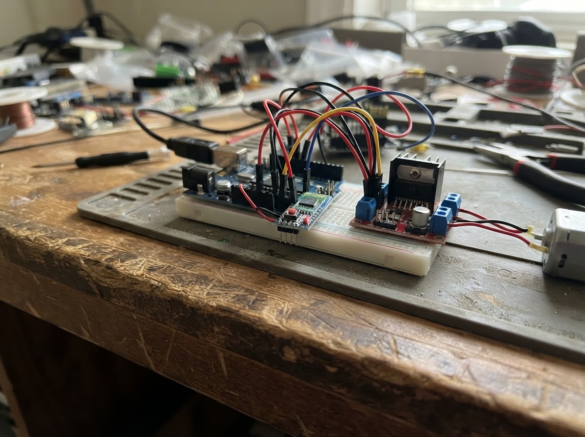
This project builds a Bluetooth-controlled robot using an Arduino Uno, HC-05 wireless module, and L298N motor driver to control two DC motors. The guide provides a complete wiring diagram, parts list, and step-by-step assembly instructions including a critical voltage divider for safe HC-05 communication.
The included firmware enables real-time motor control via Bluetooth commands, with adjustable speed and turning ratios. Builders will learn wireless communication with SoftwareSerial, motor direction control through logic pins, and PWM speed regulation—all the fundamentals for creating mobile robotics projects.
Wiring diagram

Gather all the parts
Assemble it in 6 steps
1. Prepare the Arduino Uno
Mount the Arduino Uno on your rover chassis or a breadboard. Make sure it is powered off before wiring anything.
2. Wire the HC-05 Bluetooth Module
Connect HC-05 VCC → Arduino 5V, HC-05 GND → Arduino GND, HC-05 TX → Arduino D10, HC-05 RX → Arduino D11 (through voltage divider).
- Build a voltage divider for HC-05 RX: D11 → 1kΩ → [HC-05 RX node] → 2kΩ → GND. This drops 5V to ~3.3V to protect the HC-05.
- Never connect D11 directly to HC-05 RX without the voltage divider — this can damage the module.
3. Build the voltage divider for HC-05 RX
On a small breadboard section: connect a 1kΩ resistor from D11 to a middle node, then a 2kΩ resistor from that node to GND. The middle node connects to HC-05 RX.
- You can use two 1kΩ resistors in series for the 2kΩ if needed.
4. Wire the L298N Motor Driver
Connect L298N VCC → Arduino 5V, L298N GND → Arduino GND. Then: IN1 → D2, IN2 → D4, IN3 → D7, IN4 → D8, ENA → D3, ENB → D5.
- The L298N also has a separate motor power input (VS/12V pin) — connect your motor battery pack (6–12V) here for adequate motor torque.
- The onboard 5V regulator on the L298N module can power the Arduino if your motor supply is ≤12V — connect L298N's 5V output to Arduino 5V pin and skip the USB power for standalone use.
- Do NOT connect a motor battery pack to the Arduino's 5V pin directly — only use the L298N's regulated 5V output if sharing power.
5. Connect the DC Motors
Connect the two DC drive motors to the L298N motor output terminals: Motor A (left) to OUT1/OUT2, Motor B (right) to OUT3/OUT4.
- If a motor spins the wrong direction, swap its two wires at the L298N output terminal.
6. Power up and test
Upload the firmware via Schematik's Deploy button. Open Serial Monitor at 9600 baud. Pair your phone to HC-05 (PIN: 1234 or 0000) and use a Bluetooth terminal app to send commands: F (forward), B (backward), L (left), R (right), S (stop).
- Android: use 'Serial Bluetooth Terminal' app.
- You can change the SPEED constant (0–255) in firmware to adjust motor speed.
Review all connections
1. Connections between "hc05_1" and "Arduino"
2. Connections between "l298n_1" and "Arduino"
Deploy the firmware
#include <Arduino.h>
#include <SoftwareSerial.h>

// HC-05: TX -> D10 (BT_RX), RX -> D11 (BT_TX)
// NOTE: Voltage divider (1kΩ + 2kΩ) required on D11 -> HC-05 RX to drop 5V -> 3.3V

#define BT_RX 10
#define BT_TX 11

// L298N direction pins
#define IN1 2
#define IN2 4
#define IN3 7
#define IN4 8

// L298N PWM speed pins
#define ENA 3
#define ENB 5

#define SPEED_DEFAULT 180  // 0–255, fallback speed if no slider value received
#define TURN_RATIO   0.45 // inner wheel fraction of currentSpeed (0.0=full pivot, 1.0=straight)


// Forward declarations
void stopMotors();
void moveForward(int spd);
void moveBackward(int spd);
void turnLeft(int spd);
void turnRight(int spd);

SoftwareSerial btSerial(BT_RX, BT_TX);

// ── Motor helpers ─────────────────────────────────────────────────────────────

void stopMotors() {
  digitalWrite(IN1, LOW); digitalWrite(IN2, LOW);
  digitalWrite(IN3, LOW); digitalWrite(IN4, LOW);
  analogWrite(ENA, 0);    analogWrite(ENB, 0);
}

// ── Motor truth table ────────────────────────────────────────────────────────
// Motor A (Left)  : IN1=HIGH, IN2=LOW  → forward  |  IN1=LOW,  IN2=HIGH → backward
// Motor B (Right) : IN3=LOW,  IN4=HIGH → forward  |  IN3=HIGH, IN4=LOW  → backward
//                  (B wires physically reversed, so logic is inverted)

void moveForward(int spd) {
  analogWrite(ENA, spd); analogWrite(ENB, spd);
  digitalWrite(IN1, LOW);  digitalWrite(IN2, HIGH);  // Motor A forward
  digitalWrite(IN3, HIGH); digitalWrite(IN4, LOW);   // Motor B forward
}

void moveBackward(int spd) {
  analogWrite(ENA, spd); analogWrite(ENB, spd);
  digitalWrite(IN1, HIGH); digitalWrite(IN2, LOW);   // Motor A backward
  digitalWrite(IN3, LOW);  digitalWrite(IN4, HIGH);  // Motor B backward
}

void turnLeft(int spd) {
  // Motor A backward (inner, slow), Motor B forward (outer, full) → pivot left
  int inner = (int)(spd * TURN_RATIO);
  analogWrite(ENA, inner); analogWrite(ENB, spd);
  digitalWrite(IN1, HIGH); digitalWrite(IN2, LOW);   // Motor A backward
  digitalWrite(IN3, HIGH); digitalWrite(IN4, LOW);   // Motor B forward
}

void turnRight(int spd) {
  // Motor A forward (outer, full), Motor B backward (inner, slow) → pivot right
  int inner = (int)(spd * TURN_RATIO);
  analogWrite(ENA, spd); analogWrite(ENB, inner);
  digitalWrite(IN1, LOW);  digitalWrite(IN2, HIGH);  // Motor A forward
  digitalWrite(IN3, LOW);  digitalWrite(IN4, HIGH);  // Motor B backward
}

// ── Global speed (updated by slider) ────────────────────────────────────────
int currentSpeed = SPEED_DEFAULT;  // live speed, set by slider command 'V0'–'V255'

// ── Setup ─────────────────────────────────────────────────────────────────────

void setup() {
  Serial.begin(9600);
  btSerial.begin(9600);

  pinMode(IN1, OUTPUT); pinMode(IN2, OUTPUT);
  pinMode(IN3, OUTPUT); pinMode(IN4, OUTPUT);
  pinMode(ENA, OUTPUT); pinMode(ENB, OUTPUT);

  stopMotors();

  Serial.println("Bluetooth Rover Ready!");
  Serial.println("Commands: F=Forward  B=Backward  L=Left  R=Right  S=Stop");
  Serial.println("          V0–V255=Speed slider");
}

// ── Loop ──────────────────────────────────────────────────────────────────────
// Strategy: read one byte at a time (never block).
// Direction commands are a single char (F/B/L/R/S).
// Slider commands start with 'V' followed by digits and end with '\n' or '\r'.

static String sliderBuf = "";   // accumulates digits after 'V'
static bool   inSlider  = false;

void loop() {
  while (btSerial.available()) {
    char c = (char)btSerial.read();

    // ── Slider mode: we already saw 'V', now collect digits ──────────────────
    if (inSlider) {
      if (c >= '0' && c <= '9') {
        sliderBuf += c;          // accumulate digit
      } else {
        // terminator (newline, carriage return, or next command char)
        if (sliderBuf.length() > 0) {
          currentSpeed = constrain(sliderBuf.toInt(), 0, 255);
          Serial.print(">> Speed set to "); Serial.println(currentSpeed);
        }
        sliderBuf = "";
        inSlider  = false;
        // fall through to handle 'c' as a command if it is one
        if (c == '\n' || c == '\r') continue;
      }
      if (inSlider) continue;   // still collecting digits
    }

    // ── Normal single-char command ───────────────────────────────────────────
    char cmd = toupper(c);
    switch (cmd) {
      case 'F': moveForward(currentSpeed);  Serial.println(">> Forward");  break;
      case 'B': moveBackward(currentSpeed); Serial.println(">> Backward"); break;
      case 'L': turnLeft(currentSpeed);     Serial.println(">> Left");     break;
      case 'R': turnRight(currentSpeed);    Serial.println(">> Right");    break;
      case 'S': stopMotors();               Serial.println(">> Stop");     break;
      case 'V': inSlider = true; sliderBuf = ""; break;  // start slider read
      default:  break;          // ignore newlines / unknown bytes
    }
  }
}
Remix this project
Make it yours in one click
Open a full copy of this project in your own Schematik workspace — diagram, code, parts, and assembly steps included. Swap the sensor, add features, or redesign the whole thing with AI. The author's original stays untouched.