Community project
Interactive Projector Workbench
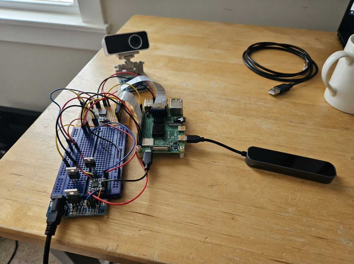
The Interactive Projector Workbench combines an ESP32 microcontroller with a TI LightCrafter Display 3310 DLP projector and Ultraleap hand gesture sensor to create a responsive projection system. This guide covers building a complete power delivery and control platform with thermal monitoring, including a protected high-side power switch, synchronous buck converter for clean 5.1 V rails, and reverse-polarity protection.
Builders will receive a complete wiring diagram, detailed parts list with sourcing information, ESP32 firmware with temperature-based thermal throttling, and step-by-step assembly instructions. The system monitors projector temperature via I2C and automatically manages power delivery to prevent overheating, while a status LED provides real-time operational feedback.
Wiring diagram

Gather all the parts
Assemble it in 6 steps
1. Mount the protected power carrier
Mount the custom power carrier on insulated standoffs inside the workbench. Keep the locking DC barrel connector at the enclosure edge, and use a regulated 19 V supply rated for at least 8 A; its centre pin goes to VIN+ and its outer sleeve goes to GND.
- Keep the input TVS diode and reverse-polarity MOSFET physically close to the barrel connector so a surge or accidental reversed supply is stopped before it reaches the rest of the bench.
- Use wide copper or short, thick wire for the 19 V input and 5.1 V output paths.
- Do not connect the 19 V input to the Raspberry Pi or Leap Motion 2; it can permanently damage 5 V equipment.
- Do not bypass the TVS diode or reverse-polarity circuit: a wrongly connected supply can damage every connected board.
2. Connect the projector power path
Connect the protected 19 V output to the projector high-side switch, then connect the switch output to the TI LightCrafter Display 3310 projector subsystem 19V_IN terminal. Connect the projector ground terminal to the same GND return. The switch input is ESP_PWR_EN from ESP32 GPIO5, so the controller can turn the projector rail off if the enclosure gets too hot.
- Keep the 19 V projector wires short and use wire sized for the projector supply current.
- Leave the projector's original power connector and internal driver board intact.
- Make sure the projector 19V_IN and GND terminals are not swapped — swapped power can damage the projector board.
- Do not power this projector subsystem from the 5.1 V rail; it requires its own 19 V input.
3. Power the Raspberry Pi and hand sensor
Connect the regulated 5.1 V output to a USB-C power-input cable or certified USB-C power board feeding the Raspberry Pi 5 USB-C power connector. Use the Pi's blue USB 3 port and a short USB 3 Type-A cable/header for the Leap Motion 2: VBUS is 5.1 V (power), GND is ground, and the SuperSpeed pairs plus D+ and D− carry data.
- Use a low-resistance USB-C power lead; voltage drop in a thin or long cable can make the Pi show an undervoltage warning.
- Keep the Leap Motion cable away from the buck inductor and projector power wires.
- Do not feed the Pi through its GPIO header for this design; use its USB-C power connector so the Pi can manage USB power correctly.
- Do not connect or disconnect the USB 3 cable while the connector is carrying loose, exposed power wiring.
4. Connect the picture cable
Run a short shielded micro-HDMI-to-HDMI cable from Raspberry Pi micro-HDMI port 0 to the intact HDMI input on the TI projector subsystem. The named pair HDMI0_CLK_P/N carries the clock and HDMI0_D0_P/N is one video data pair; the cable also carries the remaining HDMI pairs, control wires, shields, and ground required for a working link.
- Use a certified short HDMI cable rather than hand-wiring HDMI differential pairs; this prevents picture dropouts caused by signal reflections.
- Route the HDMI cable separately from the 19 V projector wiring.
- Do not attempt to connect only the named HDMI pairs; a complete shielded HDMI cable is required for reliable 1080p video.
- Do not crush or sharply bend the HDMI cable; damaged high-speed wires can cause a blank or flickering picture.
5. Install the temperature monitor and status light
Mount the TMP117 where it measures warm enclosure air, not directly on the projector heat sink. Connect V+ to 3V3_LOGIC (power), GND to GND (ground), SDA to ESP32 GPIO8 (data), and SCL to ESP32 GPIO9 (clock). Connect ESP32 GPIO4 through the 220 Ω resistor to the long LED leg, then connect the flat-side LED leg to GND; the light shows that projector power is enabled.
- Place the TMP117 near the projector exhaust path but out of direct hot-air contact, so it reacts to enclosure temperature rather than a single metal surface.
- The LED's longer lead is positive; the flat side of its body marks the negative lead.
- Make sure V+ and GND are not swapped on the TMP117 — swapped power can damage the sensor.
- Never connect the LED directly to GPIO4; the 220 Ω resistor limits current and protects the LED and ESP32 pin.
6. Inspect before applying power
With power unplugged, check that all GND connections share one return, that the 19 V projector branch cannot touch the 5.1 V Pi branch, and that every IC supply location has its nearby 100 nF and 10 µF ceramic capacitors fitted. Then plug in the 19 V supply, confirm the Pi receives 5.1 V through USB-C, and only then connect the Leap Motion 2 and HDMI cable.
- Use a multimeter first: check approximately 19 V at the projector input path, 5.1 V at the Pi power lead, and 3.3 V at the TMP117 before attaching the boards.
- Keep the projector ventilation openings clear during use.
- Stop immediately if a wire, connector, or board becomes hot; unplug the 19 V supply before investigating.
- Do not look into the projector lens at close range while it is operating.
Review all connections
1. Connections between "dc_input" and "ESP32"
2. Connections between "tvs_input" and "ESP32"
3. Connections between "reverse_mosfet" and "ESP32"
4. Connections between "buck_5v1" and "ESP32"
5. Connections between "logic_ldo" and "ESP32"
6. Connections between "pi5" and "ESP32"
7. Connections between "projector_switch" and "ESP32"
8. Connections between "projector_evm" and "ESP32"
9. Connections between "leap_motion_2" and "ESP32"
10. Connections between "temp_sensor" and "ESP32"
11. Connections between "status_led_resistor" and "ESP32"
12. Connections between "status_led" and "ESP32"
Deploy the firmware
#include <Arduino.h>
#include <Wire.h>


// Forward declarations
void setProjectorPower(bool on);
bool readTemperatureC(float &temperatureC);

constexpr int ESP_PWR_EN = 5;
constexpr int STATUS_LED_PIN = 4;
constexpr int I2C_SDA_PIN = 8;
constexpr int I2C_SCL_PIN = 9;
constexpr uint8_t TMP117_ADDRESS = 0x48;
constexpr uint8_t TMP117_TEMP_REGISTER = 0x00;
constexpr float PROJECTOR_TRIP_C = 60.0F;
constexpr float PROJECTOR_RESTART_C = 52.0F;
constexpr uint32_t SAMPLE_INTERVAL_MS = 1000;

bool sensorAvailable = false;
bool projectorEnabled = false;
uint32_t lastSampleMs = 0;

void setProjectorPower(bool on) {
  projectorEnabled = on;
  digitalWrite(ESP_PWR_EN, on ? HIGH : LOW);
  digitalWrite(STATUS_LED_PIN, on ? HIGH : LOW);
}

bool readTemperatureC(float &temperatureC) {
  Wire.beginTransmission(TMP117_ADDRESS);
  Wire.write(TMP117_TEMP_REGISTER);
  if (Wire.endTransmission(false) != 0) {
    return false;
  }

  if (Wire.requestFrom(TMP117_ADDRESS, static_cast<uint8_t>(2)) != 2) {
    return false;
  }

  int16_t rawTemperature = static_cast<int16_t>(
      (static_cast<uint16_t>(Wire.read()) << 8) | Wire.read());
  temperatureC = rawTemperature * 0.0078125F;
  return true;
}

void setup() {
  pinMode(ESP_PWR_EN, OUTPUT);
  pinMode(STATUS_LED_PIN, OUTPUT);
  setProjectorPower(false);

  Serial.begin(115200);
  Wire.begin(I2C_SDA_PIN, I2C_SCL_PIN);

  float initialTemperatureC = 0.0F;
  sensorAvailable = readTemperatureC(initialTemperatureC);
  if (sensorAvailable) {
    setProjectorPower(true);
    Serial.println("Temperature monitor ready; projector rail enabled.");
  } else {
    Serial.println("TMP117 not found; projector rail remains disabled.");
  }
}

void loop() {
  if (!sensorAvailable || millis() - lastSampleMs < SAMPLE_INTERVAL_MS) {
    return;
  }
  lastSampleMs = millis();

  float temperatureC = 0.0F;
  if (!readTemperatureC(temperatureC)) {
    setProjectorPower(false);
    Serial.println("Temperature reading failed; projector rail disabled.");
    return;
  }

  Serial.printf("Enclosure temperature: %.1f C\n", temperatureC);
  if (projectorEnabled && temperatureC >= PROJECTOR_TRIP_C) {
    setProjectorPower(false);
    Serial.println("Overtemperature: projector rail disabled.");
  } else if (!projectorEnabled && temperatureC <= PROJECTOR_RESTART_C) {
    setProjectorPower(true);
    Serial.println("Temperature recovered: projector rail enabled.");
  }
}
Remix this project
Make it yours in one click
Open a full copy of this project in your own Schematik workspace — diagram, code, parts, and assembly steps included. Swap the sensor, add features, or redesign the whole thing with AI. The author's original stays untouched.
Related projects

Create A Complete Electrical Schematic Esp32 Sma
ESP32 · September 17, 2026Ayansh Agrawal
ESP32 Kare Ekran Projeleri
ESP32 · September 16, 2026Seref Ai
Component Qty --------------------------- ------
ESP32 · September 16, 2026Yathartha Chakrawal