Community project
Je Veux Cr Er Un Objet Qui Absorbe
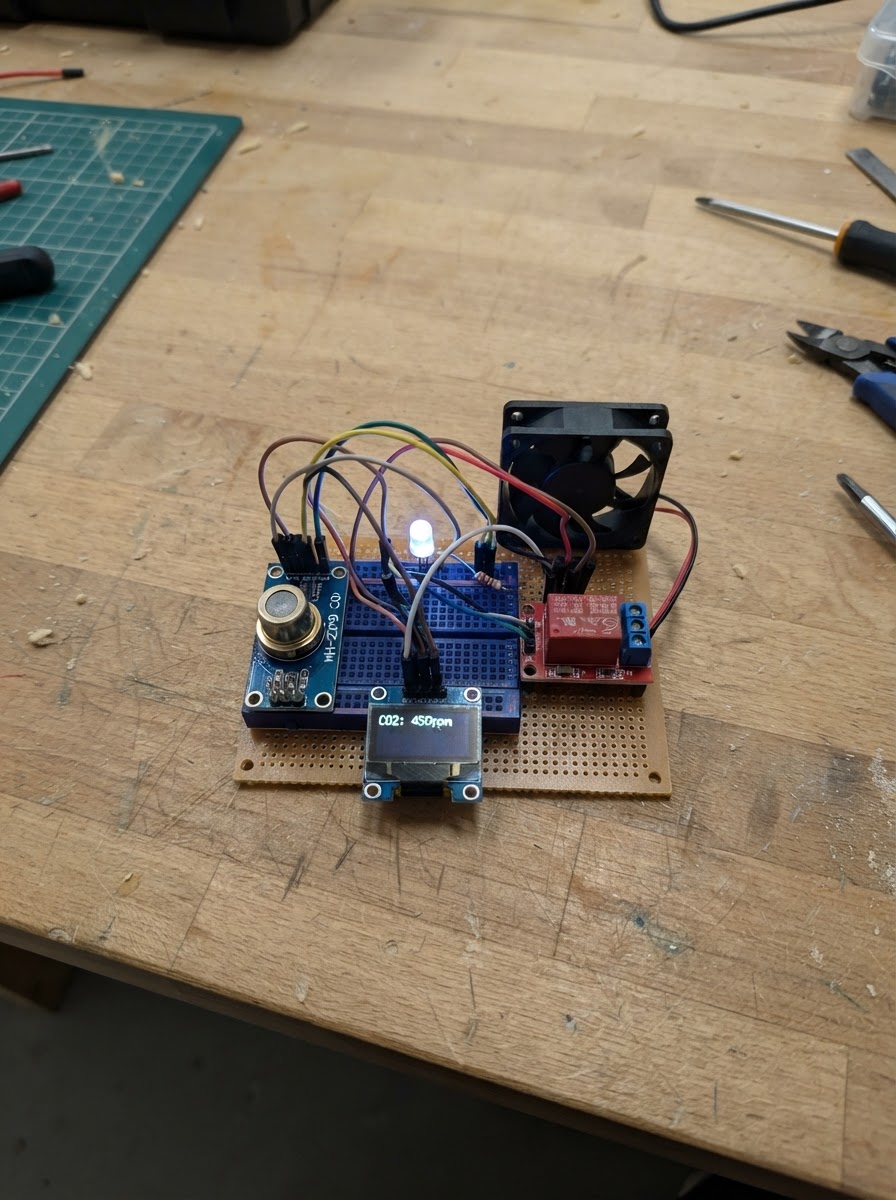
This CO2 monitoring and fan control system uses an ESP32 to read air quality data from an MH-Z19B sensor and automatically activate a ventilation fan when carbon dioxide levels exceed safe thresholds. The system displays real-time CO2 measurements on an SSD1306 OLED screen and uses an RGB LED to provide visual feedback about air quality status—green for good air, yellow for warning, and red for poor conditions.
The guide includes a complete wiring diagram, parts list, and step-by-step assembly instructions for connecting the CO2 sensor, OLED display, RGB LED with current-limiting resistors, and relay-controlled fan to the ESP32. Firmware is provided to handle sensor readings, threshold-based fan automation, display updates, and color-coded LED indicators, making this an ideal project for monitoring indoor air quality in offices, classrooms, or living spaces.
Wiring diagram

Gather all the parts
Assemble it in 5 steps
1. Power off everything
Make sure the ESP32 is unplugged from USB before wiring anything.
- Never wire components while the board is powered.
2. Wire the MH-Z19B CO₂ sensor
Connect MH-Z19B VIN → ESP32 5V, GND → GND, TXD → GPIO16, RXD → GPIO17. The sensor UART logic is 3.3V — no level shifter needed for RX/TX.
- Allow 3 minutes warm-up after first power-on before readings are valid.
3. Wire the SSD1306 OLED display
Connect OLED VCC → ESP32 3.3V, GND → GND, SDA → GPIO21, SCL → GPIO22.
4. Wire the RGB LED with resistors
Insert three 100Ω resistors in series on each color channel: GPIO25 → R1 → LED-R, GPIO27 → R2 → LED-G, GPIO14 → R3 → LED-B. Connect LED GND (common cathode) to GND.
- The long leg of each color pin is the anode; the single short leg is the common cathode.
5. Wire the relay and fan
Connect relay VCC → 5V, GND → GND, IN → GPIO26. Then wire the 5V fan's positive lead to the relay's COM terminal and the relay's NO (Normally Open) terminal to 5V. Fan negative → GND. When GPIO26 goes LOW, the relay closes and the fan runs.
- Keep relay wiring away from the breadboard signal area.
- The fan must be 5V rated — do not use a 12V fan here.
Review all connections
1. Connections between "co2_sensor" and "ESP32"
2. Connections between "oled" and "ESP32"
3. Connections between "relay" and "ESP32"
4. Connections between "res_r" and "ESP32"
5. Connections between "res_g" and "ESP32"
6. Connections between "res_b" and "ESP32"
7. Connections between "rgb_led" and "ESP32"
8. Connections between "fan" and "ESP32"
Deploy the firmware
#include <Arduino.h>
#include <Wire.h>
#include <Adafruit_GFX.h>
#include <Adafruit_SSD1306.h>
#include <MHZ19.h>
#include <HardwareSerial.h>

// Pin definitions
#define CO2_RX_PIN   16   // ESP32 RX2 ← MH-Z19B TX
#define CO2_TX_PIN   17   // ESP32 TX2 → MH-Z19B RX
#define RELAY_PIN    26   // Relay IN (LOW = fan ON)
#define LED_R_PIN    25
#define LED_G_PIN    27
#define LED_B_PIN    14

// Thresholds (ppm)
#define CO2_GOOD     800
#define CO2_WARN    1200
#define CO2_BAD     1600

// OLED
#define SCREEN_WIDTH 128
#define SCREEN_HEIGHT 64
#define OLED_RESET   -1

// Forward declarations
void setLED(uint8_t r, uint8_t g, uint8_t b);
void updateDisplay(int co2ppm, bool fan);

Adafruit_SSD1306 display(SCREEN_WIDTH, SCREEN_HEIGHT, &Wire, OLED_RESET);

// CO2 sensor
HardwareSerial co2Serial(2);
MHZ19 mhz19;

// State
int  lastCO2     = -1;
bool fanOn       = false;
unsigned long lastRead = 0;
const unsigned long READ_INTERVAL = 5000; // ms

void setLED(uint8_t r, uint8_t g, uint8_t b) {
  analogWrite(LED_R_PIN, r);
  analogWrite(LED_G_PIN, g);
  analogWrite(LED_B_PIN, b);
}

void updateDisplay(int co2ppm, bool fan) {
  display.clearDisplay();
  display.setTextColor(SSD1306_WHITE);

  // Title
  display.setTextSize(1);
  display.setCursor(0, 0);
  display.print("CO2 Capture System");
  display.drawLine(0, 10, 127, 10, SSD1306_WHITE);

  // CO2 value
  display.setTextSize(2);
  display.setCursor(0, 16);
  if (co2ppm > 0) {
    display.print(co2ppm);
    display.setTextSize(1);
    display.print(" ppm");
  } else {
    display.print("Warmup...");
  }

  // Status
  display.setTextSize(1);
  display.setCursor(0, 40);
  if (co2ppm <= 0)        display.print("Status: WARMING UP");
  else if (co2ppm < CO2_GOOD)  display.print("Status: GOOD  ");
  else if (co2ppm < CO2_WARN)  display.print("Status: MODERATE");
  else if (co2ppm < CO2_BAD)   display.print("Status: HIGH   ");
  else                         display.print("Status: DANGER !");

  // Fan
  display.setCursor(0, 52);
  display.print("Fan: ");
  display.print(fan ? "ON  (capturing)" : "OFF");

  display.display();
}

void setup() {
  Serial.begin(115200);

  // LED pins
  pinMode(LED_R_PIN, OUTPUT);
  pinMode(LED_G_PIN, OUTPUT);
  pinMode(LED_B_PIN, OUTPUT);

  // Relay
  pinMode(RELAY_PIN, OUTPUT);
  digitalWrite(RELAY_PIN, HIGH); // relay inactive (active LOW module)

  // OLED
  if (!display.begin(SSD1306_SWITCHCAPVCC, 0x3C)) {
    Serial.println("SSD1306 not found");
  }
  display.clearDisplay();
  display.setTextSize(1);
  display.setTextColor(SSD1306_WHITE);
  display.setCursor(10, 20);
  display.print("CO2 Capture System");
  display.setCursor(20, 36);
  display.print("Warming up 3 min");
  display.display();

  // CO2 sensor on UART2
  co2Serial.begin(9600, SERIAL_8N1, CO2_RX_PIN, CO2_TX_PIN);
  mhz19.begin(co2Serial);
  mhz19.autoCalibration(false);

  setLED(0, 0, 30); // dim blue during warmup
  Serial.println("MH-Z19B warming up (3 minutes needed)...");
}

void loop() {
  unsigned long now = millis();

  if (now - lastRead >= READ_INTERVAL) {
    lastRead = now;
    int co2 = mhz19.getCO2();

    if (co2 > 0) {
      // Fan logic
      bool shouldFanOn = (co2 >= CO2_WARN);
      if (shouldFanOn != fanOn) {
        fanOn = shouldFanOn;
        digitalWrite(RELAY_PIN, fanOn ? LOW : HIGH);
      }

      // LED color
      if (co2 < CO2_GOOD)       setLED(0, 255, 0);    // green
      else if (co2 < CO2_WARN)  setLED(255, 165, 0);  // orange
      else if (co2 < CO2_BAD)   setLED(255, 50, 0);   // red-orange
      else                      setLED(255, 0, 0);     // red

      if (co2 != lastCO2) {
        lastCO2 = co2;
        updateDisplay(co2, fanOn);
        Serial.printf("CO2: %d ppm  Fan: %s\n", co2, fanOn ? "ON" : "OFF");
      }
    } else {
      // Still warming up
      updateDisplay(-1, false);
    }
  }
}
Remix this project
Make it yours in one click
Open a full copy of this project in your own Schematik workspace — diagram, code, parts, and assembly steps included. Swap the sensor, add features, or redesign the whole thing with AI. The author's original stays untouched.