Community project
KK2.1.5 Quad Power Distribution Board
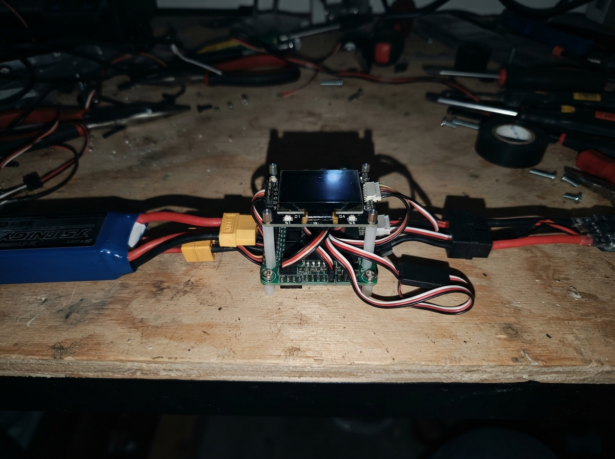
The KK2.1.5 Quad Power Distribution Board is a passive PCB that distributes battery power from a 3S LiPo pack to four ESCs while breaking out all control and sensor signals from a KK2.1.5 flight controller. Heavy copper traces handle high current delivery to each ESC independently, while a regulated 5 V UBEC safely powers the flight controller and its peripherals.
This guide provides a complete wiring diagram, parts list, and step-by-step assembly instructions for building a quad-rotor power system. The project covers connector installation, socket placement, signal routing, and critical pre-flight checks to ensure safe operation before the first battery connection.
Wiring diagram

Gather all the parts
Assemble it in 6 steps
1. Order the board with heavy copper
Have pdb_pcb_1 made as a two-layer board with 2 oz copper, a wide positive copper area, a wide ground copper area, and short equal-width branches to the four ESC terminals. Keep the battery and ESC copper clear of the central 2.54 mm KK2.1.5 socket area so the controller is never exposed to battery voltage.
- Put the XT60 at one board edge and place one ESC terminal pair toward each arm of the quadcopter.
- Use generous copper pours and several stitched vias wherever a high-current path changes sides of the board.
- Thin signal-sized tracks can overheat under motor current and can cause a fire or loss of aircraft control.
2. Fit the battery and ESC power connectors
Solder xt60_male_1 into the BAT+ and BAT− pads on pdb_pcb_1. Fit esc_terminal_1 through esc_terminal_4 into the four labelled ESC1 through ESC4 pad pairs; every V+ terminal goes to its matching positive pad and every GND terminal goes to its matching negative pad.
- Use a high-current connector or solder pads rated for at least the maximum current of the ESC on that arm.
- Mark the board clearly: BAT+, BAT−, ESC1 V+/GND, ESC2 V+/GND, ESC3 V+/GND, and ESC4 V+/GND.
- Do not swap V+ and GND — a reversed 3S LiPo connection can instantly damage an ESC, the flight controller, or the battery wiring.
- Never plug in the battery while soldering or checking continuity.
3. Install the KK2.1.5 socket footprint
Solder the 2.54 mm female header sockets into the central footprint on pdb_pcb_1 in the same row positions and orientation as every connector row on kk21_5_controller_1. Label every row exactly as printed on the controller: receiver inputs and OUT1 through OUT8. Route each signal socket straight through to a labelled breakout pad; route only the 5 V and ground bus as described below.
- Before soldering all pins, place the controller over the sockets without power to confirm that every three-pin row enters cleanly.
- Use a square pad or printed arrow to mark the signal end of every three-pin row.
- A one-column offset or reversed three-pin row can put power onto a signal contact and damage the controller or connected receiver.
4. Wire only one regulated 5 V supply to the controller
Connect bec_5v_1 VIN+ to pdb_pcb_1 BAT+ (power) and VIN− to BAT− (ground). Connect the UBEC VOUT+ to FC_5V_IN (regulated 5 V power) and VOUT− to FC_GND (ground). Plug the KK2.1.5 into its socket footprint only after checking that this supply measures 5 V, not battery voltage.
- Feed the KK2.1.5 and receiver from this one UBEC, or alternatively use exactly one ESC BEC; remove or insulate the red 5 V wires from all other ESC servo plugs.
- Keep the 5 V traces separate from the 3S battery copper except at the UBEC input.
- A fully charged 3S pack is 12.6 V. Connecting it to any KK2.1.5 5 V header pin will destroy the controller.
- Paralleling the 5 V outputs of multiple ESC BECs can make the regulators fight each other and overheat.
5. Connect the four ESCs and control signals
For each ESC, connect its red battery wire to its matching V+ terminal and its black battery wire to the matching GND terminal: ESC 1 to esc_terminal_1, ESC 2 to esc_terminal_2, ESC 3 to esc_terminal_3, and ESC 4 to esc_terminal_4. Connect the signal lead from each ESC to the matching KK output breakout: OUT1 to M1_SIG (signal), OUT2 to M2_SIG (signal), OUT3 to M3_SIG (signal), and OUT4 to M4_SIG (signal); connect every ESC signal ground to FC_GND (ground).
- Use the motor order shown in the KK2.1.5 mixer screen; terminal number and physical motor position are not automatically the same.
- Keep motor power leads short and twist each positive and negative pair together where possible to reduce electrical noise.
- Remove propellers for all first power-up, receiver checks, motor-order checks, and ESC calibration. A configuration mistake can start a motor unexpectedly.
6. Check before the first battery connection
With lipo_3s_1 disconnected, use a meter to confirm BAT+ has no short to BAT−, each ESC V+ terminal has continuity to BAT+, each ESC GND terminal has continuity to BAT−, and FC_5V_IN measures isolated from BAT+. Then plug lipo_3s_1 into xt60_male_1 and confirm the UBEC output is a steady 5 V before installing the controller.
- Use a smoke stopper or current-limited first connection if you have one.
- Secure the battery connector and UBEC so vibration cannot pull on solder joints.
- Stop immediately if a wire, connector, or board becomes warm without motors running — disconnect the battery before investigating.
Review all connections
1. Connections between "xt60_male_1" and "ESP32"
2. Connections between "pdb_pcb_1" and "ESP32"
3. Connections between "lipo_3s_1" and "ESP32"
4. Connections between "bec_5v_1" and "ESP32"
Deploy the firmware
/*
 * This project is a passive power-distribution and KK2.1.5 breakout PCB.
 * The KK2.1.5 supplies its own flight firmware; this ESP32 workspace entrypoint
 * has no control role and intentionally does not drive any hardware.
 *
 * PCB net map:
 * - XT60 BAT+ / BAT-: 3S LiPo input, 12.6 V maximum.
 * - ESC1..ESC4 V+ / GND: four parallel high-current battery branches.
 * - KK 2.54 mm sockets: AIL, ELE, THR, RUD, AUX; OUT1..OUT8;
 *   battery monitor; buzzer; and 2x3 ISP, all reproduced as labelled breakouts.
 * - Only the 5 V UBEC feeds the KK 5 V rail. Never feed 3S battery voltage
 *   into a KK header.
 */

void setup() {
  // Passive PCB: no microcontroller I/O is used.
}

void loop() {
  // Passive PCB: no recurring work is required.
}
Remix this project
Make it yours in one click
Open a full copy of this project in your own Schematik workspace — diagram, code, parts, and assembly steps included. Swap the sensor, add features, or redesign the whole thing with AI. The author's original stays untouched.
Related projects

Create A Complete Electrical Schematic Esp32 Sma
ESP32 · September 17, 2026Ayansh Agrawal
ESP32 Kare Ekran Projeleri
ESP32 · September 16, 2026Seref Ai
Component Qty --------------------------- ------
ESP32 · September 16, 2026Yathartha Chakrawal