Community project
LiFePO4 Battery Monitor
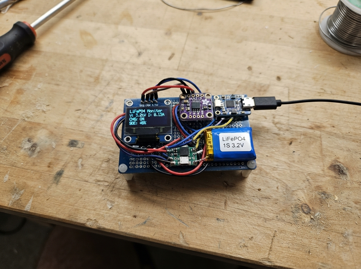
This project builds a real-time battery monitor for a 1S LiFePO4 cell using an ESP32 microcontroller. The system measures voltage, current, and power consumption through an INA219 current sensor, displays readings on an OLED screen, and estimates charge percentage based on cell voltage characteristics. The guide includes a complete wiring diagram, parts list, and firmware ready to flash.
Builders will learn how to interface multiple I2C sensors with an ESP32, implement LiFePO4 state-of-charge estimation, and create a responsive display that shows real-time charging and discharging data. Assembly takes about an hour and requires basic soldering skills to connect the battery pack, charger module, current sensor, and display.
Wiring diagram

Gather all the parts
Assemble it in 4 steps
1. Keep the battery leads safe
Leave the LiFePO4 battery disconnected while building. Connect battery_1 BAT- to the common GND rail, then connect battery_1 BAT+ to ina219_1 VIN+. This routes every battery amp through the meter.
- Use short, adequately thick wires for the two battery-positive connections.
- Do not let the battery's red and black leads touch — that can heat the wires and damage the battery.
2. Connect the charger and 3.3 V supply
Connect ina219_1 VIN- to charger_1 BAT. Connect charger_1 GND and boost_1 GND to the common GND rail. Connect charger_1 LOAD to boost_1 VIN, then connect boost_1 VOUT to the 3V3 rail. Set the boost module to exactly 3.3 V with a multimeter before attaching the ESP-12E.
- The charger USB-C socket is the input used to recharge the battery.
- Do not connect a LiFePO4 cell to a charger unless its charge setting is confirmed for 3.6 V LiFePO4 cells — a 4.2 V lithium-polymer setting can damage the cell.
- Do not exceed 3.3 V on the ESP-12E, OLED, or INA219 logic supply.
3. Wire the display and meter
Connect oled_1 VCC and ina219_1 VCC to 3V3 (power). Connect their GND pins to GND (ground). Connect both SDA pins to ESP-12E GPIO4/D2 (data), and both SCL pins to GPIO5/D1 (clock).
- The OLED and INA219 deliberately share the two SDA and SCL wires.
- Make sure VCC and GND are not swapped — swapped power can damage the OLED or sensor.
4. Power and program the ESP-12E
Connect the ESP-12E 3V3 and GND pins to the matching rails. Build the normal ESP-12E boot circuit: EN and RST held high with 10 kΩ resistors, GPIO0 held high with 10 kΩ, and GPIO15 held low with 10 kΩ. Use a 3.3 V USB-to-serial adapter for programming, temporarily holding GPIO0 at GND while resetting to enter programming mode.
- Check the 3V3 rail with a multimeter before inserting or powering the ESP-12E.
- A 5 V serial adapter connected to ESP-12E signal pins can permanently damage the module.
- Do not attach the battery until the wiring has been checked for shorts.
Review all connections
1. Connections between "battery_1" and "ESP32"
2. Connections between "ina219_1" and "ESP32"
3. Connections between "charger_1" and "ESP32"
4. Connections between "boost_1" and "ESP32"
5. Connections between "oled_1" and "ESP32"
Deploy the firmware
#include <Arduino.h>
#include <Wire.h>
#include <Adafruit_GFX.h>
#include <Adafruit_SSD1306.h>
#include <Adafruit_INA219.h>


// Forward declarations
float lifepo4Percent(float volts);
void drawScreen(float volts, float milliamps, float milliwatts);

constexpr uint8_t I2C_SDA_PIN = 4;
constexpr uint8_t I2C_SCL_PIN = 5;
constexpr uint8_t SCREEN_WIDTH = 128;
constexpr uint8_t SCREEN_HEIGHT = 64;

Adafruit_SSD1306 display(SCREEN_WIDTH, SCREEN_HEIGHT, &Wire, -1);
Adafruit_INA219 ina219;

String lastScreen = "";
unsigned long lastSampleMs = 0;

float lifepo4Percent(float volts) {
  // Resting-voltage estimate for one LiFePO4 cell; load current affects this estimate.
  if (volts >= 3.60f) return 100.0f;
  if (volts >= 3.45f) return 95.0f;
  if (volts >= 3.35f) return 80.0f;
  if (volts >= 3.30f) return 60.0f;
  if (volts >= 3.25f) return 40.0f;
  if (volts >= 3.20f) return 20.0f;
  if (volts >= 3.10f) return 10.0f;
  return 0.0f;
}

void drawScreen(float volts, float milliamps, float milliwatts) {
  float pct = lifepo4Percent(volts);
  const char *direction = milliamps > 15.0f ? "DISCHARGE" : (milliamps < -15.0f ? "CHARGING" : "IDLE");
  float amps = fabs(milliamps) / 1000.0f;
  float watts = fabs(milliwatts) / 1000.0f;

  String screen = String(volts, 3) + "|" + String(milliamps, 0) + "|" + String(milliwatts, 0) + "|" + String((int)pct) + "|" + direction;
  if (screen == lastScreen) return;
  lastScreen = screen;

  display.clearDisplay();
  display.setTextColor(SSD1306_WHITE);
  display.setTextSize(1);
  display.setCursor(0, 0);
  display.print("LiFePO4 MONITOR");
  display.setCursor(0, 13);
  display.print("Bat: "); display.print(volts, 3); display.println(" V");
  display.setCursor(0, 25);
  display.print("Current: "); display.print(amps, 3); display.println(" A");
  display.setCursor(0, 37);
  display.print("Power: "); display.print(watts, 2); display.println(" W");
  display.setCursor(0, 49);
  display.print(direction); display.print("  "); display.print((int)pct); display.println("%");
  display.display();
}

void setup() {
  Wire.begin(I2C_SDA_PIN, I2C_SCL_PIN);
  display.begin(SSD1306_SWITCHCAPVCC, 0x3C);
  display.clearDisplay();
  display.setTextColor(SSD1306_WHITE);
  display.setTextSize(1);
  display.setCursor(0, 0);
  display.println("Starting meter...");
  display.display();

  if (!ina219.begin()) {
    display.setCursor(0, 16);
    display.println("INA219 not found");
    display.display();
    while (true) delay(100);
  }
  ina219.setCalibration_32V_2A();
}

void loop() {
  if (millis() - lastSampleMs < 1000) return;
  lastSampleMs = millis();

  float volts = ina219.getBusVoltage_V() + ina219.getShuntVoltage_mV() / 1000.0f;
  float milliamps = ina219.getCurrent_mA();
  float milliwatts = ina219.getPower_mW();
  drawScreen(volts, milliamps, milliwatts);
}
Remix this project
Make it yours in one click
Open a full copy of this project in your own Schematik workspace — diagram, code, parts, and assembly steps included. Swap the sensor, add features, or redesign the whole thing with AI. The author's original stays untouched.
Related projects

Create A Complete Electrical Schematic Esp32 Sma
ESP32 · September 17, 2026Ayansh Agrawal
ESP32 Kare Ekran Projeleri
ESP32 · September 16, 2026Seref Ai
Component Qty --------------------------- ------
ESP32 · September 16, 2026Yathartha Chakrawal