Community project
Light-Seeking Solar Robot Car
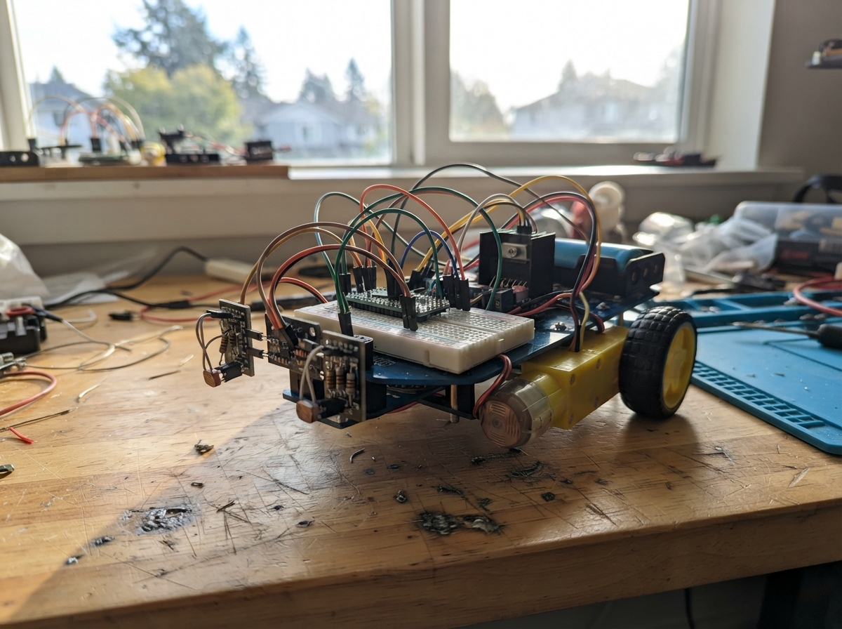
This light-seeking solar robot car autonomously tracks light sources by rotating a pan-and-tilt sensor bracket to find the brightest direction, then drives toward it using differential motor control. The robot combines an ESP32 microcontroller, dual photoresistors for light detection, TT motors with gearboxes for propulsion, and servo-driven optics to create an engaging autonomous behavior.
This guide provides a complete wiring diagram, parts list, and step-by-step assembly instructions for building the robot on a breadboard. You'll learn how to wire the L298N motor driver, configure the PCA9685 PWM servo controller, integrate dual power supplies for motors and servos, and upload firmware that implements light-seeking logic with servo panning and motor speed control.
Wiring diagram

Gather all the parts
Assemble it in 8 steps
1. Mount the wheels and light sensors
Fit left_motor and right_motor to the chassis with their shafts facing the wheels. Mount left_ldr on the front-left and right_ldr on the front-right, with a small upright divider between them so each one mainly sees light from its own side.
- Keep both light sensors at the same height so their readings can be compared fairly.
- Keep the motor wires away from the wheels; a wire pulled into a wheel can short the battery.
2. Fit the moving sensor bracket
Screw pan_servo into the lower left-right position of pan_tilt_bracket. Fit tilt_servo into the upper position and fasten the light-sensor plate to its horn. Before tightening the horn screws, place both servo arms near their middle positions so the bracket can move in both directions.
- Do not force a servo horn onto its shaft or run a servo while the bracket is blocked; it can strip the small plastic gears.
3. Build the light-reading rows on one breadboard
Use the single breadboard to make two matching sensor rows. Left: one left_ldr leg to ESP32 3V3 (power); its other leg joins one left_divider_resistor leg and GPIO34 (signal); the resistor’s remaining leg goes to ESP32 GND (ground). Right: one right_ldr leg to 3V3 (power); its other leg joins one right_divider_resistor leg and GPIO35 (signal); the resistor’s remaining leg goes to GND (ground). Keep the two joined middle rows separate; only the 3V3 and GND rows are shared.
- The photoresistors and 10 kΩ resistors work either way around.
- Use one shared solderless breadboard: its 3.3 V and GND rows can be shared by both sensor circuits.
- Never connect the sensor rows to 5 V; 5 V on GPIO34 or GPIO35 can damage the ESP32.
4. Connect the motor driver
Connect motor_driver OUT1 to left_motor M1 and OUT2 to left_motor M2 (left-wheel power). Connect OUT3 to right_motor M1 and OUT4 to right_motor M2 (right-wheel power). Connect IN1 to GPIO25, IN2 to GPIO26, IN3 to GPIO27, IN4 to GPIO14, ENA to GPIO32, and ENB to GPIO33 (motor-control signals). Connect motor_driver GND to ESP32 GND (ground).
- Remove ENA and ENB jumper caps if present, so the ESP32 can vary the wheel speed.
- If a wheel turns the wrong way, disconnect power and swap that motor’s two wires.
5. Wire the PCA9685 servo driver
Connect pca9685 VCC to ESP32 3V3 (logic power), pca9685 GND to ESP32 GND (ground), pca9685 SDA to GPIO21 (data), and pca9685 SCL to GPIO22 (clock). Connect the pan servo’s three-wire plug to PCA9685 channel 0 and the tilt servo plug to channel 1: brown/black to GND, red to V+, and orange/yellow to the signal pin.
- Do not connect either servo signal wire to GPIO16 or GPIO17; those incorrect direct connections are no longer part of this build.
6. Connect the separate servo power bank
Connect servo_power_bank 5V OUT to pca9685 V+ (servo power). Connect servo_power_bank GND OUT to the shared GND (ground). This same ground must join the PCA9685, ESP32, motor driver, and battery negative connections so the control signals have a common reference.
- Do not connect the servo power bank’s 5 V positive wire to an ESP32 GPIO, 3V3, or VIN/5V pin; it powers only the PCA9685 V+ servo rail.
7. Build the main battery supply
Put two matched protected 18650 cells into battery_holder as marked. Connect BAT+ to motor_driver VS (motor power) and boost_converter IN+ (power). Connect BAT- to boost_converter IN- (ground). Set boost_converter OUT+ to exactly 5.0 V with a multimeter before connecting it to ESP32 VIN/5V and motor_driver 5V (logic power). Connect boost_converter OUT- to the shared GND (ground).
- Do not use the removed 24 V buck converter in this two-cell battery circuit. Do not connect its wiring diagram or its output to the robot.
- Set the boost converter to 5.0 V before attaching the ESP32; a higher setting can damage it.
8. Check the new wiring before power
Lift the wheels off the table. Confirm the PCA9685 is the only source of the two servo signal wires: channel 0 runs to pan_servo and channel 1 runs to tilt_servo. Confirm the servo power bank feeds only PCA9685 V+, while every ground is shared. Then plug the ESP32 into USB and turn on the servo power bank before connecting the drive battery.
- Keep fingers, loose wires, and hair clear of the wheels and moving bracket; the robot can move when the light level changes.
Review all connections
1. Connections between "battery_holder" and "ESP32"
2. Connections between "boost_converter" and "ESP32"
3. Connections between "motor_driver" and "ESP32"
4. Connections between "left_ldr" and "ESP32"
5. Connections between "left_divider_resistor" and "ESP32"
6. Connections between "right_ldr" and "ESP32"
7. Connections between "right_divider_resistor" and "ESP32"
8. Connections between "servo_power_bank" and "ESP32"
9. Connections between "pca9685" and "ESP32"
10. Connections between "pan_servo" and "ESP32"
11. Connections between "tilt_servo" and "ESP32"
Deploy the firmware
#include <Arduino.h>
#include <Wire.h>
#include <Adafruit_PWMServoDriver.h>

constexpr int LEFT_SENSOR_PIN = 34;
constexpr int RIGHT_SENSOR_PIN = 35;
constexpr int LEFT_IN1_PIN = 25;
constexpr int LEFT_IN2_PIN = 26;
constexpr int RIGHT_IN1_PIN = 27;
constexpr int RIGHT_IN2_PIN = 14;
constexpr int LEFT_ENABLE_PIN = 32;
constexpr int RIGHT_ENABLE_PIN = 33;
constexpr int PCA9685_SDA_PIN = 21;
constexpr int PCA9685_SCL_PIN = 22;
constexpr uint8_t PAN_CHANNEL = 0;
constexpr uint8_t TILT_CHANNEL = 1;
constexpr int PAN_CENTER_DEGREES = 90;
constexpr int TILT_LEVEL_DEGREES = 90;
constexpr int PAN_MIN_DEGREES = 35;
constexpr int PAN_MAX_DEGREES = 145;
constexpr int SERVO_MIN_TICK = 102;
constexpr int SERVO_MAX_TICK = 492;
constexpr uint32_t PWM_FREQUENCY = 20000;
constexpr uint8_t PWM_RESOLUTION = 8;
constexpr int PWM_MAX = (1 << PWM_RESOLUTION) - 1;
constexpr int CRUISE_SPEED = 185;
constexpr int MIN_RUNNING_SPEED = 105;
constexpr int DARK_THRESHOLD = 160;
constexpr int TURN_DEADBAND = 90;
constexpr uint32_t CONTROL_INTERVAL_MS = 80;

Adafruit_PWMServoDriver servoDriver(0x40);
int panAngle = PAN_CENTER_DEGREES;
uint32_t lastControlTime = 0;

int readLight(int pin) {
  long total = 0;
  for (int sample = 0; sample < 8; ++sample) total += analogRead(pin);
  return total / 8;
}

uint16_t degreesToTick(int degrees) {
  return map(constrain(degrees, 0, 180), 0, 180, SERVO_MIN_TICK, SERVO_MAX_TICK);
}

void setServoAngle(uint8_t channel, int degrees) {
  servoDriver.setPWM(channel, 0, degreesToTick(degrees));
}

void setMotorDirectionForward() {
  digitalWrite(LEFT_IN1_PIN, HIGH);
  digitalWrite(LEFT_IN2_PIN, LOW);
  digitalWrite(RIGHT_IN1_PIN, HIGH);
  digitalWrite(RIGHT_IN2_PIN, LOW);
}

void setMotorSpeed(int leftSpeed, int rightSpeed) {
  ledcWrite(LEFT_ENABLE_PIN, constrain(leftSpeed, 0, PWM_MAX));
  ledcWrite(RIGHT_ENABLE_PIN, constrain(rightSpeed, 0, PWM_MAX));
}

void stopMotors() { setMotorSpeed(0, 0); }

void aimHeadAtBrighterSide(int difference) {
  int nextAngle = panAngle;
  if (difference > TURN_DEADBAND) nextAngle++;
  else if (difference < -TURN_DEADBAND) nextAngle--;
  nextAngle = constrain(nextAngle, PAN_MIN_DEGREES, PAN_MAX_DEGREES);
  if (nextAngle != panAngle) {
    panAngle = nextAngle;
    setServoAngle(PAN_CHANNEL, panAngle);
  }
}

void setup() {
  Serial.begin(115200);
  analogReadResolution(12);
  analogSetPinAttenuation(LEFT_SENSOR_PIN, ADC_11db);
  analogSetPinAttenuation(RIGHT_SENSOR_PIN, ADC_11db);
  pinMode(LEFT_IN1_PIN, OUTPUT);
  pinMode(LEFT_IN2_PIN, OUTPUT);
  pinMode(RIGHT_IN1_PIN, OUTPUT);
  pinMode(RIGHT_IN2_PIN, OUTPUT);
  ledcAttach(LEFT_ENABLE_PIN, PWM_FREQUENCY, PWM_RESOLUTION);
  ledcAttach(RIGHT_ENABLE_PIN, PWM_FREQUENCY, PWM_RESOLUTION);
  setMotorDirectionForward();
  stopMotors();
  Wire.begin(PCA9685_SDA_PIN, PCA9685_SCL_PIN);
  servoDriver.begin();
  servoDriver.setPWMFreq(50);
  setServoAngle(PAN_CHANNEL, panAngle);
  setServoAngle(TILT_CHANNEL, TILT_LEVEL_DEGREES);
}

void loop() {
  const uint32_t now = millis();
  if (now - lastControlTime < CONTROL_INTERVAL_MS) return;
  lastControlTime = now;
  const int leftLight = readLight(LEFT_SENSOR_PIN);
  const int rightLight = readLight(RIGHT_SENSOR_PIN);
  if (max(leftLight, rightLight) < DARK_THRESHOLD) {
    stopMotors();
    return;
  }
  const int difference = leftLight - rightLight;
  aimHeadAtBrighterSide(difference);
  if (abs(difference) <= TURN_DEADBAND) {
    setMotorSpeed(CRUISE_SPEED, CRUISE_SPEED);
  } else if (difference > 0) {
    const int leftSpeed = map(constrain(difference, TURN_DEADBAND, 2500), TURN_DEADBAND, 2500, CRUISE_SPEED, MIN_RUNNING_SPEED);
    setMotorSpeed(leftSpeed, CRUISE_SPEED);
  } else {
    const int rightSpeed = map(constrain(-difference, TURN_DEADBAND, 2500), TURN_DEADBAND, 2500, CRUISE_SPEED, MIN_RUNNING_SPEED);
    setMotorSpeed(CRUISE_SPEED, rightSpeed);
  }
  Serial.printf("left=%d right=%d\n", leftLight, rightLight);
}
Remix this project
Make it yours in one click
Open a full copy of this project in your own Schematik workspace — diagram, code, parts, and assembly steps included. Swap the sensor, add features, or redesign the whole thing with AI. The author's original stays untouched.