Community project
Linux Audio Mixer Controller
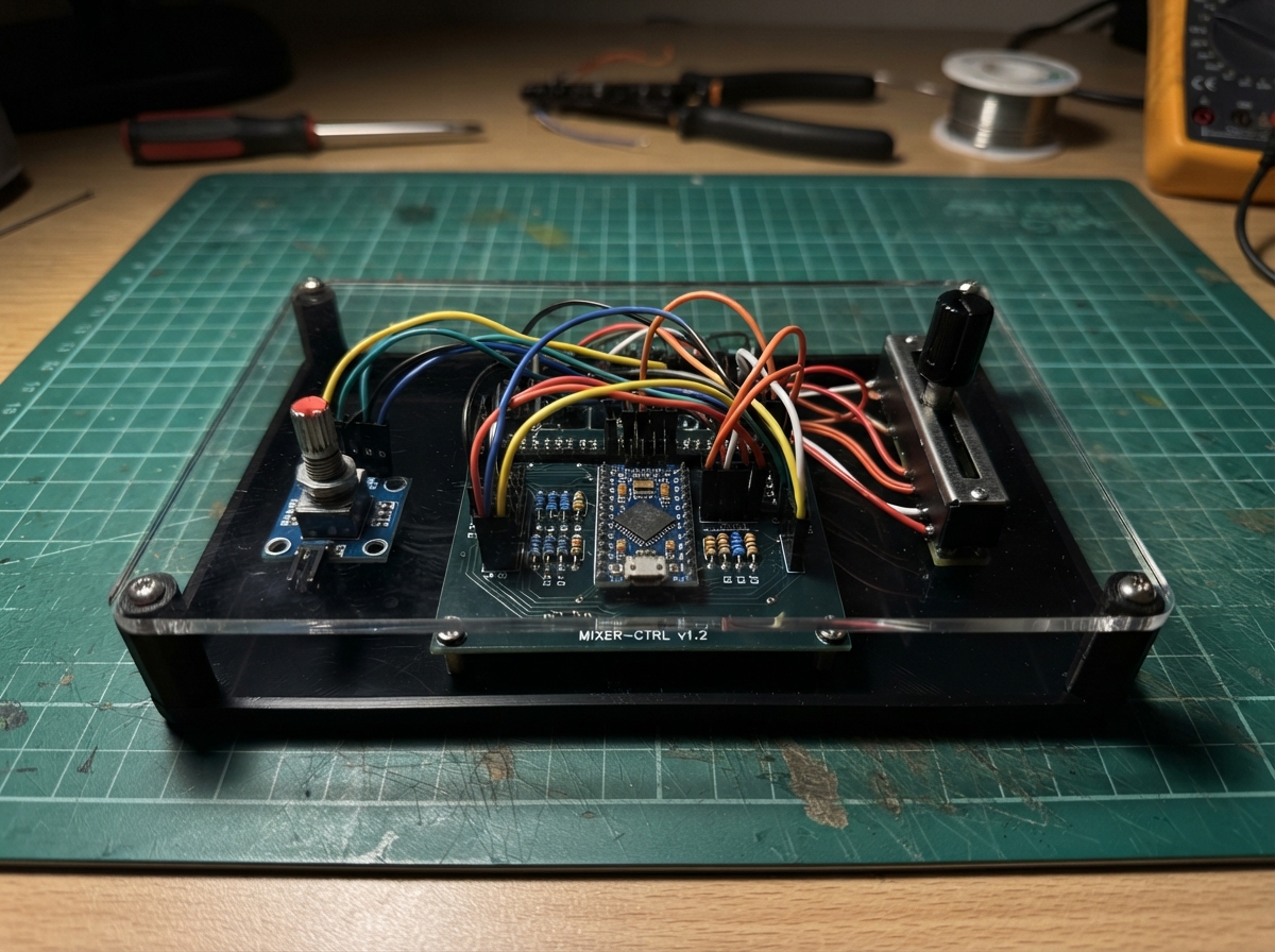
This project turns an ESP32 into a USB audio mixer controller that integrates with Linux audio systems. Four motorized faders send MIDI CC messages for volume control on different audio sinks, while individual mute buttons with LED feedback provide per-sink control. A master volume knob adjusts the main output level, and a media control encoder lets you play, pause, and skip tracks without leaving your audio application.
The guide provides a complete wiring diagram showing how to connect the rotary encoders, slide potentiometers, push buttons, and status LEDs to the ESP32's GPIO pins. You'll get a full parts list, step-by-step assembly instructions, and ready-to-flash firmware that handles MIDI CC generation, HID consumer control commands, and debouncing logic for reliable operation.
Wiring diagram

Gather all the parts
Assemble it in 8 steps
1. Place the ESP32 and controls
Put the Feather ESP32-S3, four 10 kΩ linear faders, four normally-open momentary buttons, four red LEDs, four 220 Ω resistors, and the two KY-040 encoder modules on the panel. Place each red LED beside its matching fader and mute button.
- Label each group 1 through 4 before attaching wires.
- Do not use motorized faders or connect any old motor-power supply in this hand-operated version.
2. Give every fader safe reference power
Connect one outer terminal, named VREF here, on every fader to the Feather 3V3 pin (power). Connect the opposite outer terminal, named GND here, on every fader to a Feather GND pin (ground). Use the same outer-terminal direction for all four faders so moving every slider upward means louder.
- If one fader works backward, swap only its two outer-terminal wires; leave its center wire alone.
- Never connect a fader terminal to 5 V, VIN, 10 V, or 12 V — the center terminal could send too much voltage into the Feather.
3. Connect the four slider signals
Connect fader 1 WIPER, its center terminal, to GPIO1 (signal). Connect fader 2 WIPER to GPIO2 (signal). Connect fader 3 WIPER to GPIO3 (signal). Connect fader 4 WIPER to GPIO4 (signal).
- The center terminal is often physically between the two outer terminals; check the fader drawing if its labels differ.
- Keep the center-terminal signal wires away from loose power wires, because a short to 5 V can damage an ESP32 input.
4. Wire the four sink-mute buttons
For button 1, connect GND to Feather GND (ground) and SIGNAL to GPIO5 (mute signal for sink 1). For button 2, connect GND to Feather GND (ground) and SIGNAL to GPIO6 (mute signal for sink 2). For button 3, connect GND to Feather GND (ground) and SIGNAL to GPIO7 (mute signal for sink 3). For button 4, connect GND to Feather GND (ground) and SIGNAL to GPIO8 (mute signal for sink 4).
- Each button has no positive or negative side. A quick press changes that sink between muted and unmuted.
- Use normally-open momentary buttons; a latching switch would hold the input down and make mute changes unreliable.
5. Wire the four red mute lights
For LED 1, connect GPIO9 to one lead of resistor 1 (control), connect the resistor’s other lead to the LED’s long leg (current limiting), and connect the LED’s short leg or flat-side lead to GND (ground). Repeat: GPIO10 through resistor 2 to LED 2 long leg, GPIO11 through resistor 3 to LED 3 long leg, and GPIO12 through resistor 4 to LED 4 long leg; connect every LED short leg to GND (ground).
- The red light turns on when its matching mute button puts that sink into the muted state.
- Every LED needs its own 220 Ω resistor. Do not connect an LED long leg directly to a GPIO — that can damage the LED or the Feather pin.
- Make sure the LED long and short legs are not reversed; a reversed LED will not light.
6. Wire the master knob
Connect the master KY-040 encoder VCC to Feather 3V3 (power) and GND to Feather GND (ground). Connect CLK to GPIO14 (turn signal), DT to GPIO21 (turn direction signal), and SW to GPIO38 (push-button signal).
- The knob controls MIDI master volume when turned and sends MIDI master mute while pressed.
- Make sure VCC and GND are not swapped — swapped power can damage the encoder module.
7. Wire the media knob
Connect the second KY-040 encoder VCC to Feather 3V3 (power) and GND to Feather GND (ground). Connect CLK to GPIO39 (turn signal), DT to GPIO40 (turn direction signal), and SW to GPIO41 (push-button signal).
- Turning this knob skips to the previous or next track. Pressing it starts or pauses playback.
- Make sure VCC and GND are not swapped — swapped power can damage the encoder module.
8. Connect the Feather over USB
Connect one data-capable USB cable from the Linux computer to the Feather ESP32-S3 USB connector; this provides both power and the MIDI plus media-control data.
- The sliders, buttons, and red lights need no separate power supply.
- Do not feed power into the Feather VIN pin while it is connected to the computer by USB.
Review all connections
1. Connections between "master_encoder" and "ESP32"
2. Connections between "fader_1" and "ESP32"
3. Connections between "fader_2" and "ESP32"
4. Connections between "fader_3" and "ESP32"
5. Connections between "fader_4" and "ESP32"
6. Connections between "media_encoder" and "ESP32"
7. Connections between "mute_button_1" and "ESP32"
8. Connections between "mute_button_2" and "ESP32"
9. Connections between "mute_button_3" and "ESP32"
10. Connections between "mute_button_4" and "ESP32"
11. Connections between "mute_led_resistor_1" and "ESP32"
12. Connections between "mute_led_1" and "ESP32"
13. Connections between "mute_led_resistor_2" and "ESP32"
14. Connections between "mute_led_2" and "ESP32"
15. Connections between "mute_led_resistor_3" and "ESP32"
16. Connections between "mute_led_3" and "ESP32"
17. Connections between "mute_led_resistor_4" and "ESP32"
18. Connections between "mute_led_4" and "ESP32"
Deploy the firmware
#include <Arduino.h>
#include "USB.h"
#include "USBMIDI.h"
#include "USBHIDConsumerControl.h"

// Forward declarations
uint8_t rawToMidi(int raw);
void tapConsumerKey(uint16_t key);
void sendFaderIfMoved(uint8_t index);
void readMasterEncoder();
void readMasterButton();
void readMediaEncoder();
void readMediaButton();
void readSinkMuteButtons();

USBMIDI MIDI;
USBHIDConsumerControl ConsumerControl;

constexpr uint8_t MIDI_CHANNEL = 1;
constexpr uint8_t FADER_CC[4] = {16, 17, 18, 19};
constexpr uint8_t MASTER_CC = 7;
constexpr uint8_t MUTE_CC = 20;
constexpr uint8_t SINK_MUTE_CC[4] = {21, 22, 23, 24};

constexpr uint8_t FADER_PINS[4] = {1, 2, 3, 4};
constexpr uint8_t SINK_MUTE_BUTTON_PINS[4] = {5, 6, 7, 8};
constexpr uint8_t SINK_MUTE_LED_PINS[4] = {9, 10, 11, 12};
constexpr uint8_t ENCODER_CLK_PIN = 14;
constexpr uint8_t ENCODER_DT_PIN = 21;
constexpr uint8_t ENCODER_SW_PIN = 38;
constexpr uint8_t MEDIA_ENCODER_CLK_PIN = 39;
constexpr uint8_t MEDIA_ENCODER_DT_PIN = 40;
constexpr uint8_t MEDIA_ENCODER_SW_PIN = 41;

constexpr int ADC_MIN = 40;
constexpr int ADC_MAX = 4055;
constexpr int FADER_SEND_DEADBAND = 14;
constexpr unsigned long FADER_INTERVAL_MS = 8;
constexpr unsigned long BUTTON_DEBOUNCE_MS = 25;

int lastSentRaw[4] = {-10000, -10000, -10000, -10000};
uint8_t masterValue = 100;
int lastMasterClock = HIGH;
int lastMasterButtonReading = HIGH;
int stableMasterButtonState = HIGH;
unsigned long lastMasterButtonChangeMs = 0;
int lastMediaClock = HIGH;
int lastMediaButtonReading = HIGH;
int stableMediaButtonState = HIGH;
unsigned long lastMediaButtonChangeMs = 0;
int lastSinkMuteButtonReading[4] = {HIGH, HIGH, HIGH, HIGH};
int stableSinkMuteButtonState[4] = {HIGH, HIGH, HIGH, HIGH};
unsigned long lastSinkMuteButtonChangeMs[4] = {0, 0, 0, 0};
bool sinkMuted[4] = {false, false, false, false};
unsigned long lastFaderReadMs = 0;

uint8_t rawToMidi(int raw) {
  return static_cast<uint8_t>(constrain(map(raw, ADC_MIN, ADC_MAX, 0, 127), 0, 127));
}

void tapConsumerKey(uint16_t key) {
  ConsumerControl.press(key);
  ConsumerControl.release();
}

void sendFaderIfMoved(uint8_t index) {
  const int raw = analogRead(FADER_PINS[index]);
  if (abs(raw - lastSentRaw[index]) >= FADER_SEND_DEADBAND) {
    lastSentRaw[index] = raw;
    MIDI.controlChange(FADER_CC[index], rawToMidi(raw), MIDI_CHANNEL);
  }
}

void readMasterEncoder() {
  const int clockNow = digitalRead(ENCODER_CLK_PIN);
  if (clockNow != lastMasterClock && clockNow == LOW) {
    if (digitalRead(ENCODER_DT_PIN) != clockNow) {
      if (masterValue < 127) ++masterValue;
    } else if (masterValue > 0) {
      --masterValue;
    }
    MIDI.controlChange(MASTER_CC, masterValue, MIDI_CHANNEL);
  }
  lastMasterClock = clockNow;
}

void readMasterButton() {
  const int reading = digitalRead(ENCODER_SW_PIN);
  if (reading != lastMasterButtonReading) lastMasterButtonChangeMs = millis();
  if (millis() - lastMasterButtonChangeMs >= BUTTON_DEBOUNCE_MS && reading != stableMasterButtonState) {
    stableMasterButtonState = reading;
    MIDI.controlChange(MUTE_CC, stableMasterButtonState == LOW ? 127 : 0, MIDI_CHANNEL);
  }
  lastMasterButtonReading = reading;
}

void readMediaEncoder() {
  const int clockNow = digitalRead(MEDIA_ENCODER_CLK_PIN);
  if (clockNow != lastMediaClock && clockNow == LOW) {
    if (digitalRead(MEDIA_ENCODER_DT_PIN) != clockNow) {
      tapConsumerKey(CONSUMER_CONTROL_SCAN_NEXT_TRACK);
    } else {
      tapConsumerKey(CONSUMER_CONTROL_SCAN_PREVIOUS_TRACK);
    }
  }
  lastMediaClock = clockNow;
}

void readMediaButton() {
  const int reading = digitalRead(MEDIA_ENCODER_SW_PIN);
  if (reading != lastMediaButtonReading) lastMediaButtonChangeMs = millis();
  if (millis() - lastMediaButtonChangeMs >= BUTTON_DEBOUNCE_MS && reading != stableMediaButtonState) {
    stableMediaButtonState = reading;
    if (stableMediaButtonState == LOW) {
      tapConsumerKey(CONSUMER_CONTROL_PLAY_PAUSE);
    }
  }
  lastMediaButtonReading = reading;
}

void readSinkMuteButtons() {
  for (uint8_t i = 0; i < 4; ++i) {
    const int reading = digitalRead(SINK_MUTE_BUTTON_PINS[i]);
    if (reading != lastSinkMuteButtonReading[i]) lastSinkMuteButtonChangeMs[i] = millis();
    if (millis() - lastSinkMuteButtonChangeMs[i] >= BUTTON_DEBOUNCE_MS && reading != stableSinkMuteButtonState[i]) {
      stableSinkMuteButtonState[i] = reading;
      if (stableSinkMuteButtonState[i] == LOW) {
        sinkMuted[i] = !sinkMuted[i];
        digitalWrite(SINK_MUTE_LED_PINS[i], sinkMuted[i] ? HIGH : LOW);
        MIDI.controlChange(SINK_MUTE_CC[i], sinkMuted[i] ? 127 : 0, MIDI_CHANNEL);
      }
    }
    lastSinkMuteButtonReading[i] = reading;
  }
}

void setup() {
  analogReadResolution(12);
  for (uint8_t i = 0; i < 4; ++i) {
    pinMode(FADER_PINS[i], INPUT);
    pinMode(SINK_MUTE_BUTTON_PINS[i], INPUT_PULLUP);
    pinMode(SINK_MUTE_LED_PINS[i], OUTPUT);
    digitalWrite(SINK_MUTE_LED_PINS[i], LOW);
    lastSinkMuteButtonReading[i] = digitalRead(SINK_MUTE_BUTTON_PINS[i]);
    stableSinkMuteButtonState[i] = lastSinkMuteButtonReading[i];
  }

  pinMode(ENCODER_CLK_PIN, INPUT_PULLUP);
  pinMode(ENCODER_DT_PIN, INPUT_PULLUP);
  pinMode(ENCODER_SW_PIN, INPUT_PULLUP);
  pinMode(MEDIA_ENCODER_CLK_PIN, INPUT_PULLUP);
  pinMode(MEDIA_ENCODER_DT_PIN, INPUT_PULLUP);
  pinMode(MEDIA_ENCODER_SW_PIN, INPUT_PULLUP);

  lastMasterClock = digitalRead(ENCODER_CLK_PIN);
  lastMasterButtonReading = digitalRead(ENCODER_SW_PIN);
  stableMasterButtonState = lastMasterButtonReading;
  lastMediaClock = digitalRead(MEDIA_ENCODER_CLK_PIN);
  lastMediaButtonReading = digitalRead(MEDIA_ENCODER_SW_PIN);
  stableMediaButtonState = lastMediaButtonReading;

  MIDI.begin(MIDI_CHANNEL_OMNI);
  ConsumerControl.begin();
  USB.begin();
}

void loop() {
  readMasterEncoder();
  readMasterButton();
  readMediaEncoder();
  readMediaButton();
  readSinkMuteButtons();

  if (millis() - lastFaderReadMs >= FADER_INTERVAL_MS) {
    lastFaderReadMs = millis();
    for (uint8_t i = 0; i < 4; ++i) sendFaderIfMoved(i);
  }
}
Remix this project
Make it yours in one click
Open a full copy of this project in your own Schematik workspace — diagram, code, parts, and assembly steps included. Swap the sensor, add features, or redesign the whole thing with AI. The author's original stays untouched.
Related projects

Create A Complete Electrical Schematic Esp32 Sma
ESP32 · September 17, 2026Ayansh Agrawal
ESP32 Kare Ekran Projeleri
ESP32 · September 16, 2026Seref Ai
Component Qty --------------------------- ------
ESP32 · September 16, 2026Yathartha Chakrawal