Community project
LoRa Push-To-Talk Handheld
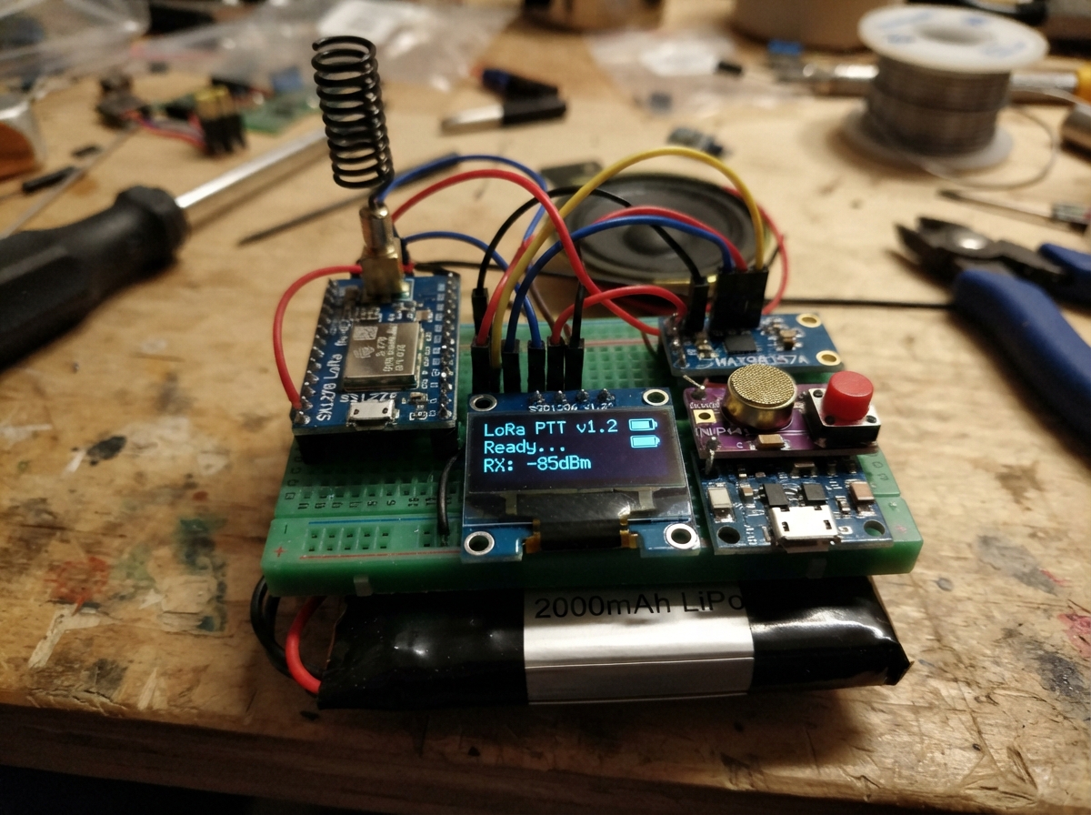
Build a pair of long-range wireless walkie-talkies using LoRa radio technology and an ESP32 microcontroller. This project combines voice transmission over the 433 MHz ISM band with real-time audio compression, letting two operators communicate across distances of several kilometers with just a push-to-talk button.
The guide provides a complete wiring diagram, full parts list, and step-by-step assembly instructions for constructing two identical units. Firmware with ADPCM audio codec, LoRa packet handling, and an OLED status display is included, along with battery charging and power management setup.
Wiring diagram

Gather all the parts
Assemble it in 6 steps
1. Siapkan dua unit yang sama
Buat dua perangkat dengan daftar bagian dan sambungan yang sama. Sebuah handy talky tidak dapat diuji sendirian: satu unit mengirim saat tombol PTT ditekan, dan unit kedua menerima suara.
- Gunakan satu antena 433 MHz pada masing-masing modul Ra-02 sebelum menyalakan perangkat.
- Pasang semua modul di meja atau breadboard dahulu; pindahkan ke kotak hanya setelah kedua unit berkomunikasi.
- Jangan menyalakan atau memancarkan Ra-02 tanpa antena 433 MHz karena bagian radio dapat rusak.
2. Buat jalur daya dan pengisian
Hubungkan kabel merah baterai ke B+ modul TP4056 dan kabel hitam baterai ke B- (daya baterai). Hubungkan OUT+ TP4056 ke VIN regulator dan OUT- TP4056 ke GND regulator (daya masuk regulator). Hubungkan VOUT regulator ke IN sakelar daya, lalu OUT sakelar ke rel 3V3 semua modul (daya yang dapat dimatikan). Hubungkan semua GND modul ke rel GND dari OUT- TP4056 (jalur balik listrik). Masukkan kabel USB 5 V hanya ke IN+ dan IN- TP4056 saat mengisi baterai.
- Gunakan TP4056 enam-pad bertanda B+/B- dan OUT+/OUT- agar perlindungan baterainya dipakai.
- Pastikan regulator benar-benar keluaran 3,3 V dan sanggup sedikitnya 500 mA.
- Jangan hubungkan baterai langsung ke ESP32, OLED, atau Ra-02; baterai penuh dapat mencapai 4,2 V dan dapat merusak bagian 3,3 V.
- Jangan sambungkan kabel USB pengisian ke OUT+ atau OUT- TP4056; sambungkan hanya ke IN+ dan IN- agar modul pengisi tidak rusak.
3. Sambungkan modul radio dan antena
Hubungkan Ra-02 VCC ke 3V3 (power), GND ke GND (ground), MOSI ke GPIO23 (data), MISO ke GPIO19 (data), SCK ke GPIO18 (clock), NSS ke GPIO4 (pilih radio), RESET ke GPIO26 (mengatur ulang radio), dan DIO0 ke GPIO33 (memberi tahu ESP32 saat radio selesai). Pasang antena 433 MHz ke konektor antena Ra-02.
- Jaga kabel antara Ra-02 dan ESP32 pendek, terutama kabel 3V3 dan GND.
- GPIO4 dipakai sebagai kabel pemilih radio; ESP32 dapat memakai pin biasa untuk tugas ini.
- Ra-02 hanya boleh diberi 3,3 V — memasukkannya ke 5 V dapat merusak modul radio.
4. Pasang layar, tombol bicara, dan mikrofon
Hubungkan OLED VCC ke 3V3 (power), GND ke GND (ground), SDA ke GPIO21 (data), dan SCL ke GPIO22 (clock). Hubungkan satu kaki tombol PTT ke GPIO27 (signal) dan kaki lainnya ke GND (ground). Hubungkan INMP441 VDD ke 3V3 (power), GND ke GND (ground), SCK ke GPIO14 (clock), WS ke GPIO25 (clock), SD ke GPIO13 (data suara), dan L/R ke GND (memilih suara mono kiri).
- Jika layar kosong, periksa tulisan kecil di modul OLED; rancangan ini memakai alamat layar umum 0x3C.
- Tombol tidak memerlukan resistor tambahan karena firmware memakai penahan sinyal di dalam ESP32.
- Pastikan VCC dan GND layar serta mikrofon tidak tertukar — daya yang terbalik dapat merusak modul.
5. Sambungkan penguat dan speaker
Hubungkan MAX98357A VIN ke 3V3 (power), GND ke GND (ground), BCLK ke GPIO14 (clock), LRC ke GPIO25 (clock), dan DIN ke GPIO32 (data suara). Hubungkan SPK+ penguat ke terminal positif speaker dan SPK- ke terminal negatif speaker (keluaran suara).
- Kabel BCLK GPIO14 dan LRC GPIO25 memang dipakai bersama oleh mikrofon dan penguat.
- Gunakan speaker 8 ohm paling tidak 1 W; suara dari speaker biasa terdengar lebih jelas daripada buzzer.
- Jangan hubungkan SPK- ke GND; kedua kabel speaker berasal dari penguat dan menghubungkannya ke GND dapat merusak penguat.
6. Nyalakan dan uji dua perangkat
Periksa sekali lagi tidak ada kabel 5 V yang masuk ke rel 3V3. Nyalakan sakelar, lalu gunakan USB papan ESP32 saat menekan Deploy di Schematik. Setelah firmware ada pada dua perangkat, tekan dan tahan PTT di unit pertama sambil berbicara dekat mikrofon; unit kedua harus berada dalam keadaan mendengarkan.
- Pada layar akan tertulis READY atau LISTENING saat siap menerima dan TALKING saat tombol ditekan.
- Jauhkan kedua antena sekitar 1 meter ketika pengujian awal agar penerima tidak terlalu dekat dengan pemancar.
- Aturan frekuensi dan daya radio berbeda menurut negara; gunakan frekuensi, antena, dan daya pancar yang diizinkan di lokasi Anda.
Review all connections
1. Connections between "lora_radio" and "ESP32"
2. Connections between "mic" and "ESP32"
3. Connections between "audio_amp" and "ESP32"
4. Connections between "screen" and "ESP32"
5. Connections between "ptt_button" and "ESP32"
6. Connections between "battery" and "ESP32"
7. Connections between "charger" and "ESP32"
8. Connections between "regulator" and "ESP32"
9. Connections between "power_switch" and "ESP32"
Deploy the firmware
#include <Arduino.h>
#include <SPI.h>
#include <LoRa.h>
#include <Wire.h>
#include <Adafruit_GFX.h>
#include <Adafruit_SSD1306.h>
#include "driver/i2s.h"


// Hoisted type definitions
struct AdpcmState {
  int predictor;
  int index;
};


// Forward declarations
void showState(const String &state, const String &detail);
uint8_t encodeSample(int sample, AdpcmState &state);
int decodeSample(uint8_t code, AdpcmState &state);
void configureAudio();
void transmitVoicePacket();
void playVoicePacket();

constexpr int LORA_CS = 4;
constexpr int LORA_RST = 26;
constexpr int LORA_DIO0 = 33;
constexpr int LORA_SCK = 18;
constexpr int LORA_MISO = 19;
constexpr int LORA_MOSI = 23;
constexpr int OLED_SDA = 21;
constexpr int OLED_SCL = 22;
constexpr int PTT_PIN = 27;
constexpr int I2S_BCLK = 14;
constexpr int I2S_LRCK = 25;
constexpr int I2S_DOUT = 32;
constexpr int I2S_DIN = 13;

constexpr long LORA_FREQUENCY = 433E6;
constexpr uint16_t SAMPLE_RATE = 4000;
constexpr size_t SAMPLES_PER_PACKET = 160; // 40 ms of voice
constexpr uint8_t PACKET_MARKER = 0x54;
constexpr uint8_t PACKET_BYTES = 83;

Adafruit_SSD1306 display(128, 64, &Wire, -1);
uint8_t packetNumber = 0;
String shownState;

const int indexTable[16] = {
  -1, -1, -1, -1, 2, 4, 6, 8,
  -1, -1, -1, -1, 2, 4, 6, 8
};
const int stepTable[89] = {
  7, 8, 9, 10, 11, 12, 13, 14, 16, 17, 19, 21, 23, 25, 28, 31,
  34, 37, 41, 45, 50, 55, 60, 66, 73, 80, 88, 97, 107, 118, 130,
  143, 157, 173, 190, 209, 230, 253, 279, 307, 337, 371, 408, 449,
  494, 544, 598, 658, 724, 796, 876, 963, 1060, 1166, 1282, 1411,
  1552, 1707, 1878, 2066, 2272, 2499, 2749, 3024, 3327, 3660, 4026,
  4428, 4871, 5358, 5894, 6484, 7132, 7845, 8630, 9493, 10442,
  11487, 12635, 13899, 15289, 16818, 18500, 20350, 22385, 24623,
  27086, 29794, 32767
};


void showState(const String &state, const String &detail) {
  String key = state + detail;
  if (key == shownState) return;
  shownState = key;
  display.clearDisplay();
  display.setTextColor(SSD1306_WHITE);
  display.setTextSize(2);
  display.setCursor(0, 4);
  display.println("HANDY");
  display.println("TALKY");
  display.setTextSize(1);
  display.setCursor(0, 44);
  display.print(state);
  display.setCursor(0, 55);
  display.print(detail);
  display.display();
}

uint8_t encodeSample(int sample, AdpcmState &state) {
  int step = stepTable[state.index];
  int diff = sample - state.predictor;
  uint8_t code = 0;
  if (diff < 0) {
    code = 8;
    diff = -diff;
  }
  int delta = step >> 3;
  if (diff >= step) { code |= 4; diff -= step; delta += step; }
  step >>= 1;
  if (diff >= step) { code |= 2; diff -= step; delta += step; }
  step >>= 1;
  if (diff >= step) { code |= 1; delta += step; }
  if (code & 8) state.predictor -= delta;
  else state.predictor += delta;
  state.predictor = constrain(state.predictor, -32768, 32767);
  state.index = constrain(state.index + indexTable[code], 0, 88);
  return code;
}

int decodeSample(uint8_t code, AdpcmState &state) {
  int step = stepTable[state.index];
  int delta = step >> 3;
  if (code & 4) delta += step;
  if (code & 2) delta += step >> 1;
  if (code & 1) delta += step >> 2;
  if (code & 8) state.predictor -= delta;
  else state.predictor += delta;
  state.predictor = constrain(state.predictor, -32768, 32767);
  state.index = constrain(state.index + indexTable[code & 0x0F], 0, 88);
  return state.predictor;
}

void configureAudio() {
  i2s_config_t config = {};
  config.mode = (i2s_mode_t)(I2S_MODE_MASTER | I2S_MODE_TX | I2S_MODE_RX);
  config.sample_rate = SAMPLE_RATE;
  config.bits_per_sample = I2S_BITS_PER_SAMPLE_32BIT;
  config.channel_format = I2S_CHANNEL_FMT_ONLY_LEFT;
  config.communication_format = I2S_COMM_FORMAT_STAND_I2S;
  config.intr_alloc_flags = 0;
  config.dma_buf_count = 8;
  config.dma_buf_len = 128;
  config.use_apll = false;
  config.tx_desc_auto_clear = true;
  config.fixed_mclk = 0;
  i2s_driver_install(I2S_NUM_0, &config, 0, nullptr);

  i2s_pin_config_t pins = {};
  pins.bck_io_num = I2S_BCLK;
  pins.ws_io_num = I2S_LRCK;
  pins.data_out_num = I2S_DOUT;
  pins.data_in_num = I2S_DIN;
  i2s_set_pin(I2S_NUM_0, &pins);
  i2s_zero_dma_buffer(I2S_NUM_0);
}

void transmitVoicePacket() {
  int32_t samples[SAMPLES_PER_PACKET];
  size_t bytesRead = 0;
  i2s_read(I2S_NUM_0, samples, sizeof(samples), &bytesRead, portMAX_DELAY);
  if (bytesRead != sizeof(samples)) return;

  uint8_t payload[PACKET_BYTES] = {};
  int16_t first = (int16_t)(samples[0] >> 16);
  AdpcmState state = { first, 0 };
  payload[0] = PACKET_MARKER;
  payload[1] = packetNumber++;
  payload[2] = (uint8_t)(first & 0xFF);
  payload[3] = (uint8_t)((first >> 8) & 0xFF);
  for (size_t i = 1; i < SAMPLES_PER_PACKET; i++) {
    int16_t input = (int16_t)(samples[i] >> 16);
    uint8_t nibble = encodeSample(input, state);
    size_t byteIndex = 4 + (i - 1) / 2;
    if ((i - 1) & 1) payload[byteIndex] |= nibble << 4;
    else payload[byteIndex] = nibble;
  }

  LoRa.idle();
  LoRa.beginPacket();
  LoRa.write(payload, sizeof(payload));
  LoRa.endPacket();
  LoRa.receive();
}

void playVoicePacket() {
  int length = LoRa.parsePacket();
  if (length != PACKET_BYTES) return;
  uint8_t payload[PACKET_BYTES];
  for (int i = 0; i < PACKET_BYTES; i++) {
    if (!LoRa.available()) return;
    payload[i] = (uint8_t)LoRa.read();
  }
  if (payload[0] != PACKET_MARKER) return;

  AdpcmState state = { (int16_t)(payload[2] | (payload[3] << 8)), 0 };
  int32_t out[SAMPLES_PER_PACKET];
  out[0] = ((int32_t)state.predictor) << 16;
  for (size_t i = 1; i < SAMPLES_PER_PACKET; i++) {
    uint8_t packed = payload[4 + (i - 1) / 2];
    uint8_t nibble = ((i - 1) & 1) ? (packed >> 4) : (packed & 0x0F);
    out[i] = ((int32_t)decodeSample(nibble, state)) << 16;
  }
  size_t written = 0;
  i2s_write(I2S_NUM_0, out, sizeof(out), &written, portMAX_DELAY);
}

void setup() {
  pinMode(PTT_PIN, INPUT_PULLUP);
  Wire.begin(OLED_SDA, OLED_SCL);
  display.begin(SSD1306_SWITCHCAPVCC, 0x3C);
  showState("Starting", "433 MHz");

  configureAudio();
  SPI.begin(LORA_SCK, LORA_MISO, LORA_MOSI, LORA_CS);
  LoRa.setPins(LORA_CS, LORA_RST, LORA_DIO0);
  if (!LoRa.begin(LORA_FREQUENCY)) {
    showState("RADIO ERROR", "check Ra-02");
    while (true) delay(1000);
  }
  LoRa.setTxPower(17);
  LoRa.setSignalBandwidth(500E3);
  LoRa.setSpreadingFactor(6);
  LoRa.setCodingRate4(5);
  LoRa.enableCrc();
  LoRa.receive();
  showState("READY", "hold PTT");
}

void loop() {
  if (digitalRead(PTT_PIN) == LOW) {
    showState("TALKING", "release to listen");
    transmitVoicePacket();
  } else {
    showState("LISTENING", "press PTT");
    playVoicePacket();
  }
}
Remix this project
Make it yours in one click
Open a full copy of this project in your own Schematik workspace — diagram, code, parts, and assembly steps included. Swap the sensor, add features, or redesign the whole thing with AI. The author's original stays untouched.