Community project
LoRa Survivor Detection Beacon
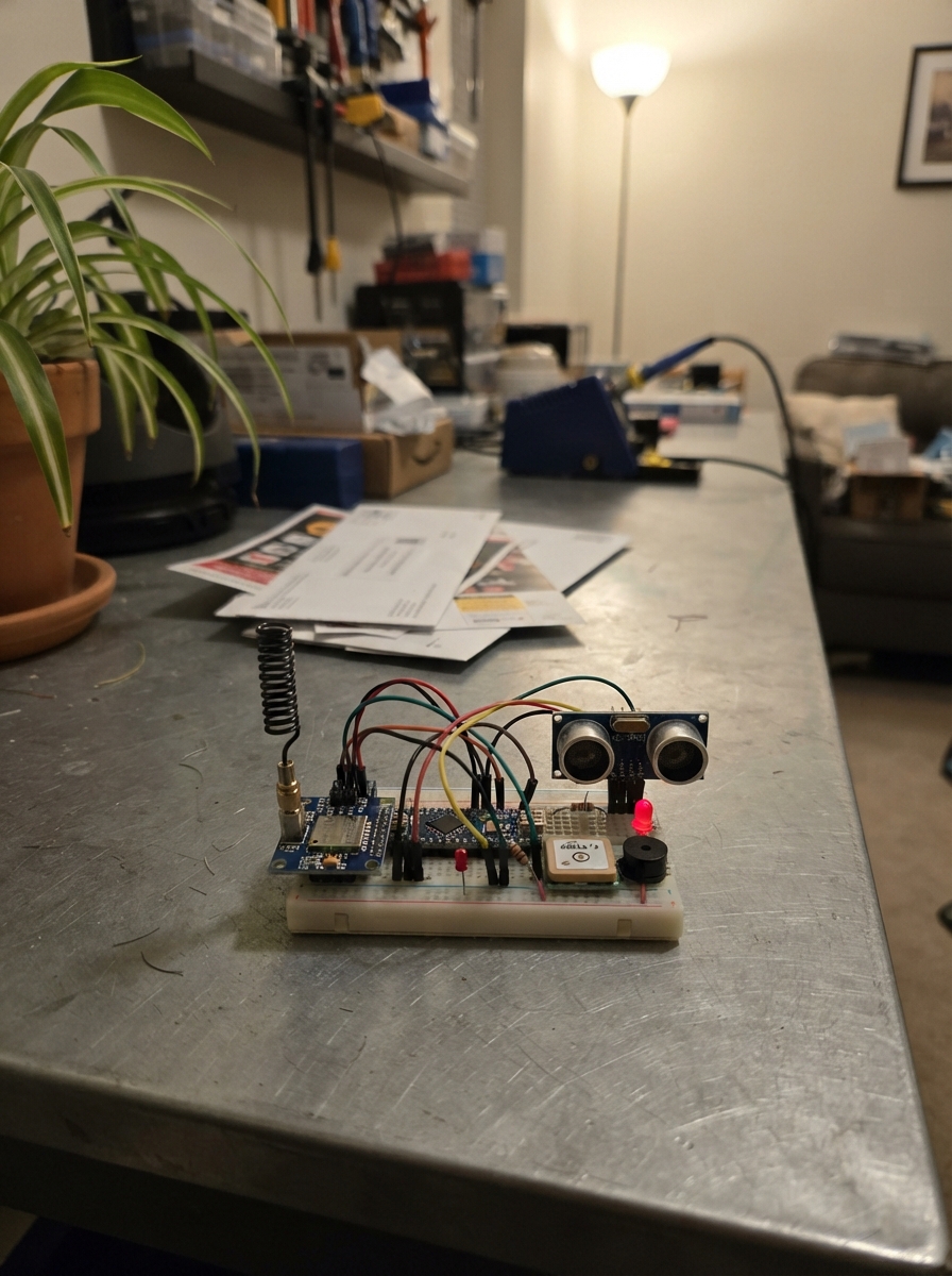
The LoRa Survivor Detection Beacon is a long-range wireless emergency locator built around an ESP32 microcontroller. It combines ultrasonic motion sensing, GPS positioning, and LoRa radio transmission to create a deployable rescue aid that can detect movement and broadcast location data across kilometers without cellular infrastructure.
This guide provides a complete parts list, wiring diagram, and step-by-step assembly instructions for building the beacon. You'll learn how to integrate the SX1278 LoRa module, HC-SR04 ultrasonic sensor, L76S GPS receiver, and alert outputs into a functional payload. The included firmware handles motion detection logic, GPS data parsing, packet encoding with error checking, and reliable LoRa transmission to establish contact with rescue networks.
Wiring diagram

Gather all the parts
Assemble it in 7 steps
1. Keep both radio antennas fitted
Screw the 433 MHz antenna onto the gold connector of each RA-02 radio module before either ESP32 is powered. The antenna gives the radio a safe path to send its signal.
- Keep the two boards at least a metre apart during the first test so the radios are not right on top of each other.
- Do not power an RA-02 radio without its antenna attached; transmitting without one can stress the radio module.
2. Build the heartbeat light
Put the green LED on the breadboard. Connect ESP32 GPIO2 to one end of the 330 Ω resistor, then connect the other resistor end to the LED long leg. Connect the LED short leg to GND. This makes the light blink once each second when the payload is running.
- The long LED leg is the positive leg. If it does not light, turn the LED around after unplugging USB.
- Do not connect the LED directly to GPIO2; the 330 Ω resistor prevents excessive current that can damage the LED or board pin.
3. Wire the ultrasonic survivor sensor
Connect HC-SR04 VCC to 3V3 (power), GND to GND (ground), TRIG to GPIO25 (signal), and ECHO to GPIO32 (signal). Power it from 3V3, not 5V, so its ECHO signal stays at a safe level for the ESP32.
- Point the two round sensor openings toward the area where you will move a hand or object during the demo.
- Do not swap VCC and GND; swapped power can damage the sensor. Do not feed its ECHO pin from a 5 V supply into GPIO32.
4. Wire the GPS receiver
Connect the L76S VCC to 3V3 (power) and GND to GND (ground). Cross the two data wires: GPS TX goes to ESP32 GPIO16 (data in), and GPS RX goes to ESP32 GPIO17 (data out).
- For a first satellite fix, place the GPS antenna side near a window or outdoors with a clear view of the sky.
- Do not swap VCC and GND; swapped power can damage the GPS module. A first GPS fix can take a minute or more and is not required for the proximity alert demo.
5. Wire the alert buzzer
Connect the buzzer red or positive lead to GPIO27 (signal) and its black or negative lead to GND (ground). It makes a short chirp when an alert packet is sent.
- This buzzer is quieter at 3.3 V than at its 5 V rating, so hold it close when testing.
- Make sure the red and black buzzer leads are not swapped; reversed wiring can stop it from sounding.
6. Wire the RA-02 radio
Connect RA-02 VCC to 3V3 (power), GND to GND (ground), NSS/CS to GPIO13 (select signal), RESET to GPIO14 (reset signal), DIO0 to GPIO26 (radio-ready signal), SCK to GPIO18 (clock), MISO to GPIO19 (data back), and MOSI to GPIO23 (data out).
- Read the labels on the RA-02 itself one wire at a time: GPIO18 is SCK, GPIO19 is MISO, and GPIO23 is MOSI.
- Do not connect RA-02 VCC to 5V; it needs 3.3 V. Mixing up GPIO18, GPIO19, and GPIO23 is the most common reason the radio does not start.
7. Power and deploy the payload board
Check that every module ground wire reaches an ESP32 GND pin, then power this bench build through the ESP32 USB connector. The USB connection powers the 3.3 V rail used by the sensor, GPS, and radio.
- After deployment, wait through the three-second startup settle. Move an object from outside the 120 cm zone into the 4–120 cm zone to trigger an alert.
- For the bench test, use USB only. Never connect a bare 3.3 V battery to VIN; VIN needs a higher input voltage.
Review all connections
1. Connections between "lora_ra02_1" and "ESP32"
2. Connections between "ultrasonic_1" and "ESP32"
3. Connections between "gps_l76s_1" and "ESP32"
4. Connections between "buzzer_1" and "ESP32"
5. Connections between "resistor_led_1" and "ESP32"
6. Connections between "led_heartbeat_1" and "ESP32"
Deploy the firmware
#include <Arduino.h>
#include <SPI.h>
#include <LoRa.h>
#include <TinyGPS++.h>
#include "rescue_net_config.h"

#define LORA_SS 13
#define LORA_RST 14
#define LORA_DIO0 26
#define ULTRASONIC_TRIG 25
#define ULTRASONIC_ECHO 32
#define LED_PIN 2
#define BUZZER_PIN 27


// Forward declarations
uint8_t crc8(const uint8_t *data, size_t length);
void putU16LE(uint8_t *out, uint16_t value);
void putI32LE(uint8_t *out, int32_t value);
float measureCm();
void pruneEdges(uint32_t now);
void addEdge(uint32_t now);
uint8_t motionCount(uint32_t now);
void sensorsUpdate(uint32_t now);
bool hasMotion(uint32_t now);
bool newEdge(uint32_t now);
bool repeatedMotion(uint32_t now);
bool gpsBegin();
void gpsFeed();
void buildPacket(uint8_t type, uint8_t motion, bool motionNow, uint8_t frame[20]);
void sendFrame(uint8_t type, uint32_t now);
void chirp(uint32_t now);

constexpr int GPS_RX_PIN = 16;
constexpr int GPS_TX_PIN = 17;
constexpr uint8_t FRAME_LEN = 20;

TinyGPSPlus gps;
HardwareSerial gpsSerial(2);

bool inBand = false;
uint32_t lastSampleMs = 0;
uint32_t lastEdgeMs = 0;
uint32_t lastNewEdgeMs = 0;
uint32_t edgeHistory[MAX_EDGE_HISTORY] = {};
uint8_t edgeWriteIndex = 0;
uint32_t lastSendMs = 0;
uint32_t buzzerOffMs = 0;
bool radioReady = false;

uint8_t crc8(const uint8_t *data, size_t length) {
  uint8_t crc = 0x00;
  while (length--) {
    crc ^= *data++;
    for (uint8_t bit = 0; bit < 8; ++bit) {
      crc = (crc & 0x80) ? static_cast<uint8_t>((crc << 1) ^ 0x07) : static_cast<uint8_t>(crc << 1);
    }
  }
  return crc;
}

void putU16LE(uint8_t *out, uint16_t value) {
  out[0] = static_cast<uint8_t>(value);
  out[1] = static_cast<uint8_t>(value >> 8);
}

void putI32LE(uint8_t *out, int32_t value) {
  uint32_t raw = static_cast<uint32_t>(value);
  out[0] = static_cast<uint8_t>(raw);
  out[1] = static_cast<uint8_t>(raw >> 8);
  out[2] = static_cast<uint8_t>(raw >> 16);
  out[3] = static_cast<uint8_t>(raw >> 24);
}

float measureCm() {
  digitalWrite(ULTRASONIC_TRIG, LOW);
  delayMicroseconds(2);
  digitalWrite(ULTRASONIC_TRIG, HIGH);
  delayMicroseconds(10);
  digitalWrite(ULTRASONIC_TRIG, LOW);
  const unsigned long duration = pulseIn(ULTRASONIC_ECHO, HIGH, 20000UL);
  return duration == 0 ? -1.0f : static_cast<float>(duration) * 0.0343f / 2.0f;
}

void pruneEdges(uint32_t now) {
  for (uint8_t i = 0; i < MAX_EDGE_HISTORY; ++i) {
    if (edgeHistory[i] != 0 && now - edgeHistory[i] > MOTION_WINDOW_MS) edgeHistory[i] = 0;
  }
}

void addEdge(uint32_t now) {
  edgeHistory[edgeWriteIndex] = now;
  edgeWriteIndex = static_cast<uint8_t>((edgeWriteIndex + 1) % MAX_EDGE_HISTORY);
  lastEdgeMs = now;
  lastNewEdgeMs = now;
}

uint8_t motionCount(uint32_t now) {
  pruneEdges(now);
  uint8_t count = 0;
  for (uint8_t i = 0; i < MAX_EDGE_HISTORY; ++i) if (edgeHistory[i] != 0) ++count;
  return count;
}

void sensorsUpdate(uint32_t now) {
  if (now - lastSampleMs < ULTRASONIC_SAMPLE_MS) return;
  lastSampleMs = now;
  const float cm = measureCm();
  const bool nowInBand = cm >= ULTRASONIC_MIN_CM && cm <= ULTRASONIC_MAX_CM;
  if (nowInBand && !inBand && (lastEdgeMs == 0 || now - lastEdgeMs >= EDGE_DEBOUNCE_MS)) addEdge(now);
  inBand = nowInBand;
}

bool hasMotion(uint32_t now) { return inBand || (lastEdgeMs != 0 && now - lastEdgeMs <= MOTION_WINDOW_MS); }
bool newEdge(uint32_t now) { return lastNewEdgeMs != 0 && now - lastNewEdgeMs <= EDGE_ACTIVE_MS; }
bool repeatedMotion(uint32_t now) { return motionCount(now) >= REPEAT_EDGE_MIN; }

bool gpsBegin() {
  const uint32_t bauds[] = {9600, 115200, 38400, 57600};
  for (uint32_t baud : bauds) {
    gpsSerial.end();
    gpsSerial.begin(baud, SERIAL_8N1, GPS_RX_PIN, GPS_TX_PIN);
    const uint32_t started = millis();
    uint8_t dollarCount = 0;
    while (millis() - started < 900) {
      while (gpsSerial.available()) {
        const char c = static_cast<char>(gpsSerial.read());
        gps.encode(c);
        if (c == '$') ++dollarCount;
      }
      if (dollarCount >= 3) return true;
      delay(1);
    }
  }
  return false;
}

void gpsFeed() { while (gpsSerial.available()) gps.encode(static_cast<char>(gpsSerial.read())); }

void buildPacket(uint8_t type, uint8_t motion, bool motionNow, uint8_t frame[FRAME_LEN]) {
  const bool fixed = gps.location.isValid() && gps.location.age() < 10000;
  uint8_t flags = 0;
  if (motionNow) flags |= 0x01;
  if (fixed) flags |= 0x10;
  frame[0] = 0xAA;
  frame[1] = MODULE_ID;
  frame[2] = type;
  frame[3] = flags;
  frame[4] = motion;
  putU16LE(&frame[5], 0); // MIC_ENABLED = 0
  putU16LE(&frame[7], 0); // BATTERY_PIN = -1
  putI32LE(&frame[9], fixed ? static_cast<int32_t>(gps.location.lat() * 10000000.0) : 0);
  putI32LE(&frame[13], fixed ? static_cast<int32_t>(gps.location.lng() * 10000000.0) : 0);
  putU16LE(&frame[17], fixed && gps.altitude.isValid() ? static_cast<uint16_t>(max(0.0, gps.altitude.meters())) : 0);
  frame[19] = crc8(frame, 19);
}

void sendFrame(uint8_t type, uint32_t now) {
  uint8_t frame[FRAME_LEN];
  buildPacket(type, motionCount(now), hasMotion(now), frame);
  LoRa.beginPacket();
  LoRa.write(frame, FRAME_LEN);
  LoRa.endPacket();
  Serial.print("[FRAME] ");
  for (uint8_t i = 0; i < FRAME_LEN; ++i) {
    if (frame[i] < 16) Serial.print('0');
    Serial.print(frame[i], HEX);
    Serial.print(i == FRAME_LEN - 1 ? '\n' : ' ');
  }
}

void chirp(uint32_t now) {
  digitalWrite(BUZZER_PIN, HIGH);
  buzzerOffMs = now + 120;
}

void setup() {
  Serial.begin(115200);
  pinMode(LED_PIN, OUTPUT);
  pinMode(BUZZER_PIN, OUTPUT);
  pinMode(ULTRASONIC_TRIG, OUTPUT);
  pinMode(ULTRASONIC_ECHO, INPUT);
  digitalWrite(ULTRASONIC_TRIG, LOW);
  digitalWrite(BUZZER_PIN, LOW);
  gpsBegin();

  SPI.begin(18, 19, 23, LORA_SS);
  LoRa.setPins(LORA_SS, LORA_RST, LORA_DIO0);
  radioReady = LoRa.begin(LORA_FREQ);
  if (radioReady) {
    LoRa.setSpreadingFactor(9);
    LoRa.setCodingRate4(5);
    LoRa.setSyncWord(0x12);
    LoRa.setTxPower(20);
  }

  const uint32_t settleUntil = millis() + 3000;
  while (millis() < settleUntil) {
    digitalWrite(LED_PIN, (millis() / 250) % 2);
    delay(10);
  }
  digitalWrite(LED_PIN, LOW);
  lastEdgeMs = 0;
  lastNewEdgeMs = 0;
  memset(edgeHistory, 0, sizeof(edgeHistory));
}

void loop() {
  const uint32_t now = millis();
  if (!radioReady) {
    digitalWrite(LED_PIN, (now / 150) % 2);
    return;
  }
  gpsFeed();
  sensorsUpdate(now);
  if (buzzerOffMs != 0 && static_cast<int32_t>(now - buzzerOffMs) >= 0) {
    digitalWrite(BUZZER_PIN, LOW);
    buzzerOffMs = 0;
  }

  const bool alert = newEdge(now) || repeatedMotion(now);
  const uint32_t interval = alert ? SEND_INTERVAL_MS_HIGH : SEND_INTERVAL_MS;
  if (now - lastSendMs >= interval) {
    sendFrame(alert ? 1 : 0, now);
    lastSendMs = now;
    if (alert) chirp(now);
  }
  digitalWrite(LED_PIN, (now / 500) % 2);
}
Remix this project
Make it yours in one click
Open a full copy of this project in your own Schematik workspace — diagram, code, parts, and assembly steps included. Swap the sensor, add features, or redesign the whole thing with AI. The author's original stays untouched.
Related projects

Create A Complete Electrical Schematic Esp32 Sma
ESP32 · September 17, 2026Ayansh Agrawal
ESP32 Kare Ekran Projeleri
ESP32 · September 16, 2026Seref Ai
Component Qty --------------------------- ------
ESP32 · September 16, 2026Yathartha Chakrawal