Community project
smart dc power
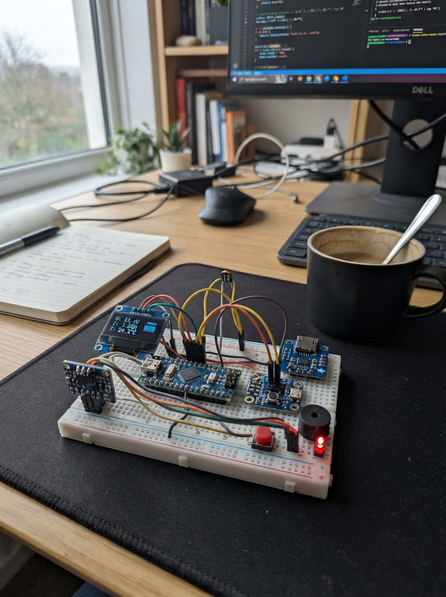
This smart DC power monitor tracks voltage, current, and temperature in real time using an ESP32 microcontroller. It displays readings on an OLED screen and logs data to an optional SD card, making it ideal for testing power supplies, battery chargers, and other DC equipment. The guide includes a complete wiring diagram, parts list, and step-by-step assembly instructions.
The monitor uses an INA219 current sensor to measure draw up to 1.5 A, an ADS1115 ADC to read an NTC thermistor, and status LEDs with a buzzer to alert when current or temperature exceed safe thresholds. Firmware is provided with configurable alarm limits, and the assembly process takes about an hour with basic soldering skills.
Wiring diagram

Gather all the parts
Assemble it in 7 steps
1. Power the monitor from USB
Place the ESP32 across the breadboard center gap and plug it into USB for power. Run one black jumper from an ESP32 GND pin to the breadboard ground rail and one red jumper from its 3V3 pin to a separate 3.3 V rail. The DC system being watched must never power the ESP32.
- USB powers the monitor and is also used when you press Deploy later.
- Do not connect a monitored source to the ESP32 3V3, 5V, or VIN pins; this can damage the board.
2. Build the temperature and current sensor connections
Power the INA219 and ADS1115 from 3V3 and GND: INA219 VCC → 3V3 (power), INA219 GND → GND (ground), ADS1115 VDD → 3V3 (power), and ADS1115 GND → GND (ground). Join INA219 SDA and ADS1115 SDA to GPIO21 (data), and join both SCL pins to GPIO22 (clock). Connect ADS1115 ADDR → GND (address choice). Connect the fixed 10 kΩ resistor from 3V3 to ADS1115 AIN1, connect the NTC SENSE lead to that same AIN1 point (temperature signal), and connect the NTC's other lead → GND (ground).
- Tape the small NTC sensor firmly to the outside of the battery, regulator, solar controller, or other part whose temperature matters.
- All of these modules share the two GPIO21/GPIO22 wires; that is normal.
- Make sure VCC and GND are not swapped — swapped power can damage the sensor boards.
- Use only 3.3 V for these module power pins so their data wires stay safe for the ESP32.
3. Connect the OLED screen
Connect OLED VCC → 3V3 (power), OLED GND → GND (ground), OLED SDA → GPIO21 (data), and OLED SCL → GPIO22 (clock). This joins the same shared sensor wires.
- The screen should show the monitor name and values after deployment.
- Make sure VCC and GND are not swapped — swapped power can damage the screen.
4. Wire the lights, buzzer, and buttons
Connect the buzzer SIGNAL → GPIO27 (alarm signal) and buzzer GND → GND (ground). Wire GPIO13 through the green LED's 220 Ω resistor to its long leg, GPIO14 through the yellow LED's 220 Ω resistor to its long leg, and GPIO26 through the red LED's 220 Ω resistor to its long leg; connect each LED short leg → GND (ground). Connect one leg of the first push button → GPIO32 (acknowledge signal) and its other leg → GND; connect one leg of the second push button → GPIO33 (save-log signal) and its other leg → GND.
- The green light means normal, yellow means a caution, and red means an alarm or disconnected temperature sensor.
- GPIO32 silences the current warning; GPIO33 saves one reading to the SD card.
- Never connect an LED directly to a GPIO; its 220 Ω resistor prevents excessive current.
5. Add the optional SD card logger
Connect the 3.3 V-compatible MicroSD module: VCC → 3V3 (power), GND → GND (ground), MISO → GPIO19 (data back from card), MOSI → GPIO23 (data to card), SCK → GPIO18 (clock), and CS → GPIO4 (card-select signal). Insert a formatted MicroSD card if you want a reading saved every 10 seconds.
- The live display and alarms still work if there is no card installed.
- The saved file is named dc_monitor.csv.
- Use a MicroSD module that accepts 3.3 V signals; a 5 V-only board can damage the ESP32.
6. Place the current monitor in the positive wire
With the DC source switched off, connect its positive wire to the fuse IN terminal, then connect fuse OUT to INA219 VIN+. Connect INA219 VIN- to the positive input of the DC load you want to watch. Connect the DC source negative, DC load negative, and the ESP32 ground rail together as one shared return. The monitored power path is source positive → 1.5 A fuse → INA219 VIN+ → INA219 VIN- → load positive.
- Use short, suitably thick wires for this power path; the thin breadboard jumpers are only for the low-power monitor wiring.
- The INA219 reads up to 26 V, but this build's 1.5 A fuse means it is intended for loads at or below 1.5 A.
- Connect the INA219 only in the positive wire as shown. Reversing VIN+ and VIN- makes the current reading negative and defeats the intended fused path.
- Switch the source off before moving a power wire; loose live DC wires can overheat or short out.
7. Check it before connecting equipment
Check every ground connection, then plug in USB and confirm the OLED is running before connecting the monitored source. Attach the NTC to the part being protected, switch on the source, and confirm the green light and live voltage, current, power, temperature, and used energy readings. Press the GPIO32 button to silence a warning after you have checked the cause.
- The built-in limits are yellow at 50 °C or 1.20 A and red at 60 °C or 1.40 A.
- The monitor warns you; it does not automatically switch the monitored power off.
- Do not exceed 26 V at INA219 VIN+ or 1.5 A through the included fuse.
- A red light or rapid beeping means stop and investigate the heat or current before continuing.
Review all connections
1. Connections between "test_fuse_1" and "ESP32"
2. Connections between "ina219_1" and "ESP32"
3. Connections between "ads1115_1" and "ESP32"
4. Connections between "ntc_fixed_resistor_1" and "ESP32"
5. Connections between "ntc_1" and "ESP32"
6. Connections between "oled_1" and "ESP32"
7. Connections between "microsd_1" and "ESP32"
8. Connections between "start_button_1" and "ESP32"
9. Connections between "stop_button_1" and "ESP32"
10. Connections between "buzzer_1" and "ESP32"
11. Connections between "reuse_led_resistor_1" and "ESP32"
12. Connections between "reuse_led_1" and "ESP32"
13. Connections between "inspect_led_resistor_1" and "ESP32"
14. Connections between "inspect_led_1" and "ESP32"
15. Connections between "recycle_led_resistor_1" and "ESP32"
16. Connections between "recycle_led_1" and "ESP32"
Deploy the firmware
#include <Wire.h>
#include <SPI.h>
#include <SD.h>
#include <Adafruit_ADS1X15.h>
#include <Adafruit_INA219.h>
#include <Adafruit_GFX.h>
#include <Adafruit_SSD1306.h>

constexpr int SD_CS_PIN = 4;
constexpr int ACK_BUTTON_PIN = 32;
constexpr int LOG_BUTTON_PIN = 33;
constexpr int BUZZER_PIN = 27;
constexpr int NORMAL_LED_PIN = 13;
constexpr int WARNING_LED_PIN = 14;
constexpr int ALARM_LED_PIN = 26;

constexpr float NTC_BETA = 3950.0f;
constexpr float NTC_R0 = 10000.0f;
constexpr float NTC_T0_K = 298.15f;
constexpr float CAUTION_TEMP_C = 50.0f;
constexpr float ALARM_TEMP_C = 60.0f;
constexpr float CAUTION_CURRENT_A = 1.20f;
constexpr float ALARM_CURRENT_A = 1.40f;
constexpr unsigned long SAMPLE_PERIOD_MS = 1000UL;
constexpr unsigned long LOG_PERIOD_MS = 10000UL;

enum Status { NORMAL, CAUTION, ALARM, SENSOR_FAULT };

Adafruit_ADS1115 ads;
Adafruit_INA219 ina219;
Adafruit_SSD1306 display(128, 64, &Wire, -1);

bool sdReady = false;
bool alarmAcknowledged = false;
bool lastAckPressed = false;
bool lastLogPressed = false;
unsigned long lastSampleMs = 0;
unsigned long lastLogMs = 0;
unsigned long previousSampleMs = 0;
float busVoltageV = 0.0f;
float currentA = 0.0f;
float temperatureC = NAN;
float energyWh = 0.0f;
Status status = SENSOR_FAULT;

float readTemperatureC() {
  int16_t raw = ads.readADC_SingleEnded(1);
  float nodeVolts = ads.computeVolts(raw);
  if (nodeVolts <= 0.01f || nodeVolts >= 3.29f) return NAN;
  float ntcOhms = NTC_R0 * nodeVolts / (3.3f - nodeVolts);
  float inverseKelvin = (1.0f / NTC_T0_K) + log(ntcOhms / NTC_R0) / NTC_BETA;
  return (1.0f / inverseKelvin) - 273.15f;
}

Status determineStatus() {
  if (isnan(temperatureC)) return SENSOR_FAULT;
  float magnitudeA = fabsf(currentA);
  if (temperatureC >= ALARM_TEMP_C || magnitudeA >= ALARM_CURRENT_A) return ALARM;
  if (temperatureC >= CAUTION_TEMP_C || magnitudeA >= CAUTION_CURRENT_A) return CAUTION;
  return NORMAL;
}

const char *statusText(Status value) {
  switch (value) {
    case NORMAL: return "NORMAL";
    case CAUTION: return "CAUTION";
    case ALARM: return "ALARM";
    default: return "CHECK TEMP SENSOR";
  }
}

void setIndicators(Status value) {
  digitalWrite(NORMAL_LED_PIN, value == NORMAL ? HIGH : LOW);
  digitalWrite(WARNING_LED_PIN, value == CAUTION ? HIGH : LOW);
  digitalWrite(ALARM_LED_PIN, (value == ALARM || value == SENSOR_FAULT) ? HIGH : LOW);
}

void drawScreen() {
  display.clearDisplay();
  display.setTextColor(SSD1306_WHITE);
  display.setTextSize(1);
  display.setCursor(0, 0);
  display.println("DC SAFETY MONITOR");
  display.print("V: "); display.print(busVoltageV, 2); display.println(" V");
  display.print("I: "); display.print(currentA, 3); display.println(" A");
  display.print("P: "); display.print(busVoltageV * currentA, 2); display.println(" W");
  display.print("T: ");
  if (isnan(temperatureC)) display.println("--.- C");
  else { display.print(temperatureC, 1); display.println(" C"); }
  display.print("Used: "); display.print(energyWh, 3); display.println(" Wh");
  display.print("State: "); display.println(statusText(status));
  display.display();
}

void appendLog(const char *reason) {
  if (!sdReady) return;
  File log = SD.open("/dc_monitor.csv", FILE_APPEND);
  if (!log) return;
  log.print(millis()); log.print(',');
  log.print(busVoltageV, 3); log.print(',');
  log.print(currentA, 4); log.print(',');
  log.print(busVoltageV * currentA, 3); log.print(',');
  if (isnan(temperatureC)) log.print("nan");
  else log.print(temperatureC, 2);
  log.print(',');
  log.print(energyWh, 4); log.print(',');
  log.print(statusText(status)); log.print(',');
  log.println(reason);
  log.close();
}

void takeSample() {
  unsigned long now = millis();
  busVoltageV = ina219.getBusVoltage_V();
  currentA = ina219.getCurrent_mA() / 1000.0f;
  temperatureC = readTemperatureC();
  if (previousSampleMs != 0) {
    float elapsedHours = (now - previousSampleMs) / 3600000.0f;
    float positivePowerW = max(0.0f, busVoltageV * currentA);
    energyWh += positivePowerW * elapsedHours;
  }
  previousSampleMs = now;
  Status oldStatus = status;
  status = determineStatus();
  if (status == NORMAL || status != oldStatus) alarmAcknowledged = false;
  setIndicators(status);
  drawScreen();
  if ((status == ALARM || status == SENSOR_FAULT) && !alarmAcknowledged) tone(BUZZER_PIN, 2400, 180);
  else if (status == CAUTION && !alarmAcknowledged) tone(BUZZER_PIN, 1200, 80);
}

void setup() {
  pinMode(ACK_BUTTON_PIN, INPUT_PULLUP);
  pinMode(LOG_BUTTON_PIN, INPUT_PULLUP);
  pinMode(BUZZER_PIN, OUTPUT);
  pinMode(NORMAL_LED_PIN, OUTPUT);
  pinMode(WARNING_LED_PIN, OUTPUT);
  pinMode(ALARM_LED_PIN, OUTPUT);
  setIndicators(SENSOR_FAULT);
  Wire.begin(21, 22);
  display.begin(SSD1306_SWITCHCAPVCC, 0x3C);
  ads.begin(0x48);
  ads.setGain(GAIN_ONE);
  ina219.begin();
  SPI.begin(18, 19, 23, SD_CS_PIN);
  sdReady = SD.begin(SD_CS_PIN, SPI);
  if (sdReady && !SD.exists("/dc_monitor.csv")) {
    File log = SD.open("/dc_monitor.csv", FILE_WRITE);
    if (log) {
      log.println("milliseconds,volts,amps,watts,temp_c,energy_wh,state,reason");
      log.close();
    }
  }
  takeSample();
  lastSampleMs = millis();
  lastLogMs = millis();
}

void loop() {
  bool ackPressed = digitalRead(ACK_BUTTON_PIN) == LOW;
  bool logPressed = digitalRead(LOG_BUTTON_PIN) == LOW;
  if (ackPressed && !lastAckPressed) {
    alarmAcknowledged = true;
    noTone(BUZZER_PIN);
  }
  if (logPressed && !lastLogPressed) appendLog("manual");
  lastAckPressed = ackPressed;
  lastLogPressed = logPressed;
  unsigned long now = millis();
  if (now - lastSampleMs >= SAMPLE_PERIOD_MS) {
    lastSampleMs = now;
    takeSample();
  }
  if (sdReady && now - lastLogMs >= LOG_PERIOD_MS) {
    lastLogMs = now;
    appendLog("periodic");
  }
}
Remix this project
Make it yours in one click
Open a full copy of this project in your own Schematik workspace — diagram, code, parts, and assembly steps included. Swap the sensor, add features, or redesign the whole thing with AI. The author's original stays untouched.