Community project
Smart Home Security And Irrigation
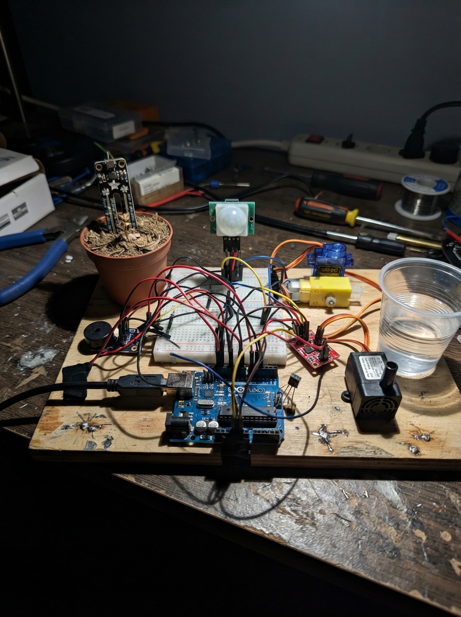
This smart home security and irrigation system combines motion detection, environmental monitoring, and automated control into a single ESP32-based platform. The project integrates dual PIR motion sensors for entry and room monitoring, soil moisture and temperature sensors for plant care, and motorized components including a servo-controlled door, buzzer alarm, and water pump for irrigation.
Builders will receive a complete wiring diagram, detailed parts list, Arduino firmware with Bluetooth connectivity, and step-by-step assembly instructions. The guide covers breadboard layout, power distribution, sensor calibration, MOSFET motor control configuration, and dry-run testing procedures to ensure all security and irrigation functions operate reliably before deployment.
Wiring diagram

Gather all the parts
Assemble it in 7 steps
1. Coloca la protoboard y el ESP32
Pon la protoboard pequeña sobre una mesa seca, con los rieles largos de color rojo y azul hacia los bordes. Coloca el ESP32 a un lado de la protoboard, no atravesado sobre ella, para que sus pines sigan accesibles. Reserva el riel rojo para 5 V de la fuente externa y el riel azul para GND; usarás las filas centrales para unir señales y componentes.
- Las cinco perforaciones de cada fila central están unidas entre sí. Los rieles largos sirven para repartir alimentación.
- Algunas protoboards pequeñas tienen los rieles partidos por la mitad; si el tuyo es así, une cada mitad que necesites con un cable Dupont corto.
- No conectes todavía la fuente externa de 5 V ni el cable USB mientras colocas cables: un cable puesto en la fila equivocada puede causar un cortocircuito.
2. Prepara la alimentación compartida
Conecta el positivo de la fuente externa de 5 V al riel rojo de la protoboard (power) y su negativo al riel azul (ground). Lleva un cable Dupont desde GND del ESP32 al riel azul (ground). Alimenta el ESP32 solamente con su propio cable USB; la fuente externa mueve el servo, la bomba y el motor.
- La tierra compartida —el riel azul unido a GND del ESP32— permite que las señales de control funcionen correctamente.
- No conectes el riel rojo de 5 V al pin 3V3 del ESP32: esos 5 V pueden dañar la placa.
3. Conecta los dos sensores de movimiento
En el PIR de puerta conecta VCC al riel rojo de 5 V (power), GND al riel azul de GND (ground) y OUT a GPIO32 mediante un adaptador de nivel de 5 V a 3.3 V (signal). En el PIR de luces conecta VCC al riel rojo de 5 V (power), GND al riel azul de GND (ground) y OUT a GPIO33 mediante otro canal del adaptador de nivel (signal).
- Deja alrededor de un minuto después de encenderlos: los PIR necesitan estabilizarse antes de detectar de forma fiable.
- No conectes OUT de un PIR alimentado a 5 V directamente al ESP32: puede enviar una señal demasiado alta y dañar la entrada.
4. Conecta los sensores de tierra y temperatura
En el sensor de humedad de suelo conecta VCC a 3V3 del ESP32 (power), GND al riel azul (ground) y OUT a GPIO34 (signal). En el TMP36, mirando su cara plana, conecta el pin izquierdo Vs a 3V3 del ESP32 (power), el pin central Vout a GPIO35 (signal) y el pin derecho GND al riel azul (ground). Puedes usar filas libres de la protoboard para mantener cada unión firme.
- No conectes la salida analógica del sensor de humedad a 5 V: podría enviar más de 3.3 V al ESP32 y dañarlo.
5. Conecta el servo, buzzer y luz
Conecta el cable rojo del servo al riel rojo de 5 V (power), el cable marrón o negro al riel azul (ground) y el cable naranja o amarillo a GPIO27 mediante un adaptador de nivel compatible (signal). Conecta SIGNAL del buzzer a GPIO26 (signal) y GND al riel azul (ground). Coloca el LED cruzando la ranura central: conecta GPIO25 a una pata de la resistencia de 220 Ω (signal), la otra pata de la resistencia a la pata larga del LED (signal), y la pata corta del LED al riel azul (ground).
- No alimentes el servo desde el pin 3V3 del ESP32: al moverse puede reiniciar la placa.
- No conectes el LED directamente a GPIO25: la resistencia limita la corriente para proteger el LED y el ESP32.
6. Conecta la bomba y el ventilador mediante los MOSFET
En el MOSFET de bomba conecta VCC al riel rojo de 5 V (power), GND al riel azul (ground), IN a GPIO16 (signal), LOAD+ al cable positivo de la bomba (power) y LOAD- al cable negativo de la bomba (signal). En el MOSFET de ventilador conecta VCC al riel rojo de 5 V (power), GND al riel azul (ground), IN a GPIO17 (signal), LOAD+ al terminal positivo del motor amarillo (power) y LOAD- al otro terminal del motor (signal). Coloca la manguera en la salida de la bomba y fija el motor con su hélice al cartón.
- Usa módulos MOSFET que acepten señales de 3.3 V. Una placa IRF520 común puede no encender bien con el ESP32.
- Mantén la bomba, la manguera y los cables de motor lejos de la protoboard: el agua sobre los contactos puede causar un cortocircuito.
7. Monta la maqueta y prueba en seco
Fija el brazo del servo a la puerta de cartón cuando esté cerrada. Pon un recipiente con tierra seca bajo la manguera y otro con tierra húmeda para comparar. Apunta el PIR de puerta al acceso y el segundo PIR a la zona de luces. Antes de añadir agua, comprueba sobre una superficie seca que el servo, LED, buzzer y ventilador respondan.
- En MIT App Inventor conecta BluetoothClient al dispositivo CasaESP32. Envía OPEN para abrir la puerta, ALARM_ON para encender la alarma y ALARM_OFF para apagarla; muestra el texto recibido con BluetoothClient.ReceiveText.
Review all connections
1. Connections between "motor_supply" and "ESP32"
2. Connections between "pir_door" and "ESP32"
3. Connections between "pir_lights" and "ESP32"
4. Connections between "soil_sensor" and "ESP32"
5. Connections between "temperature_sensor" and "ESP32"
6. Connections between "servo_door" and "ESP32"
7. Connections between "buzzer_alarm" and "ESP32"
8. Connections between "motion_led_resistor" and "ESP32"
9. Connections between "motion_led" and "ESP32"
10. Connections between "pump_mosfet" and "ESP32"
11. Connections between "fan_mosfet" and "ESP32"
Deploy the firmware
#include <Arduino.h>
#include <BluetoothSerial.h>
#include <ESP32Servo.h>

BluetoothSerial SerialBT;
Servo servoPuerta;

// Pines reales ya cableados en este proyecto.
#define PIR_ENTRADA 32
#define PIR_HABITACION 33
#define TMP1 35
#define HUMEDAD 34
#define MOSFET 16
#define LED1 25
#define SERVO_PIN 27
#define BUZZER 26
#define MOTOR_DC 17

int humedadValor = 0;
int temperaturaValor = 0;
bool alarmaActiva = false;

void setup() {
  Serial.begin(115200);
  SerialBT.begin("CasaInteligenteESP32");
  servoPuerta.setPeriodHertz(50);
  servoPuerta.attach(SERVO_PIN, 500, 2400);

  pinMode(PIR_ENTRADA, INPUT);
  pinMode(PIR_HABITACION, INPUT);
  pinMode(TMP1, INPUT);
  pinMode(HUMEDAD, INPUT);
  pinMode(MOSFET, OUTPUT);
  pinMode(LED1, OUTPUT);
  pinMode(BUZZER, OUTPUT);
  pinMode(MOTOR_DC, OUTPUT);
  analogReadResolution(12);

  digitalWrite(MOSFET, LOW);
  digitalWrite(LED1, LOW);
  digitalWrite(MOTOR_DC, LOW);
  digitalWrite(BUZZER, LOW);
  servoPuerta.write(0);
  SerialBT.println("Casa inteligente lista");
}

void loop() {
  // PIR de entrada: abre la puerta y avisa a MIT App Inventor.
  if (digitalRead(PIR_ENTRADA) == HIGH) {
    servoPuerta.write(90);
    SerialBT.println("Movimiento detectado: puerta abierta");
  } else {
    servoPuerta.write(0);
    SerialBT.println("Movimiento no detectado: puerta cerrada");
    if (alarmaActiva) {
      digitalWrite(BUZZER, HIGH);
      SerialBT.println("Alarma activada por movimiento no detectado");
    } else {
      digitalWrite(BUZZER, LOW);
    }
  }

  // El proyecto tiene un LED físico: se enciende con el PIR de habitación.
  if (digitalRead(PIR_HABITACION) == HIGH) {
    digitalWrite(LED1, HIGH);
  } else {
    digitalWrite(LED1, LOW);
  }

  temperaturaValor = analogRead(TMP1);
  if (temperaturaValor > 2000) {
    digitalWrite(MOTOR_DC, HIGH);
    SerialBT.println("Temperatura alta: ventilador encendido");
  } else {
    digitalWrite(MOTOR_DC, LOW);
  }

  humedadValor = analogRead(HUMEDAD);
  if (humedadValor < 2000) {
    digitalWrite(MOSFET, HIGH);
    SerialBT.println("Tierra seca: bomba activada");
  } else {
    digitalWrite(MOSFET, LOW);
    SerialBT.println("Tierra humeda: bomba apagada");
  }

  if (SerialBT.available()) {
    char dato = static_cast<char>(SerialBT.read());
    if (dato == 'A') {
      servoPuerta.write(90);
      SerialBT.println("Puerta abierta desde app");
    } else if (dato == 'C') {
      servoPuerta.write(0);
      SerialBT.println("Puerta cerrada desde app");
    } else if (dato == 'B') {
      alarmaActiva = true;
      SerialBT.println("Alarma activada desde app");
    } else if (dato == 'S') {
      alarmaActiva = false;
      digitalWrite(BUZZER, LOW);
      SerialBT.println("Alarma desactivada desde app");
    }
  }

  delay(300);
}
Remix this project
Make it yours in one click
Open a full copy of this project in your own Schematik workspace — diagram, code, parts, and assembly steps included. Swap the sensor, add features, or redesign the whole thing with AI. The author's original stays untouched.